


Description
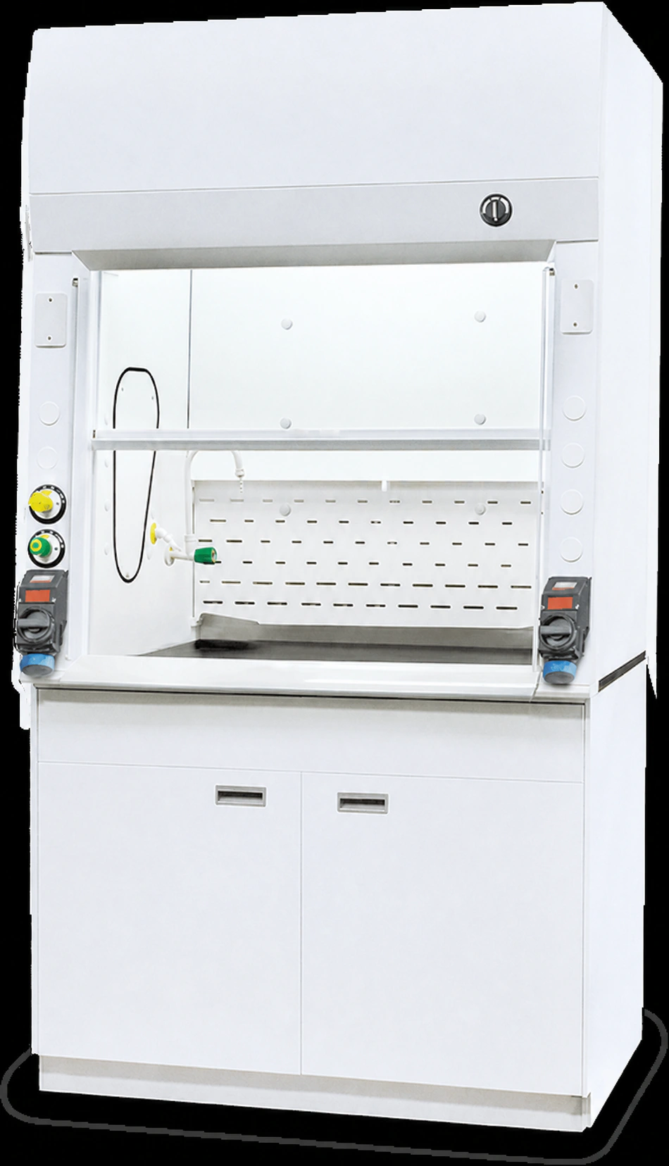
An explosion-proof fume hood is a ducted laboratory enclosure configured to reduce electrical ignition-source risk where a documented flammable-gas or vapor hazard requires hazardous-location controls. Room air enters through the sash opening, carries process vapors through the work chamber and leaves through a connected exhaust system. The cabinet provides the controlled work zone, while the project classification determines how lights, switches, receptacles, sensors, wiring, the fan motor and other electrical devices are selected or located.
The explosion-proof fume hood name does not assign a Class/Division or Zone rating and does not mean that the cabinet can contain a blast. XICHENG configures the hood around the process, classified-area document, apparatus envelope, chemical exposure, selected electrical strategy and building exhaust arrangement. The approved drawing and component schedule identify the cabinet construction, sash and work zone, supplied electrical components and interfaces; the project documents define the connected fan, duct, field wiring, grounding, controls and site acceptance.
Explosion-Proof Fume Hood for Flammable Vapor Applications
What Is
The hazardous-location fume hood combines the normal capture function of a ducted chemical hood with a project-specific strategy for electrical equipment that could become an ignition source. The hood still depends on inward airflow at the operating sash position to move vapors away from the operator and into the exhaust path. Its specialized identity comes from coordinating that airflow function with the actual hazardous-location requirements rather than adding a general-purpose electrical package to a standard cabinet.
The work chamber, liner, baffle, worktop, sash and service penetrations are selected for the chemicals, temperature, cleaning method and apparatus used in the process. These physical materials address corrosion, cleaning, heat and mechanical use. They do not establish an electrical rating. A stainless-steel chamber, a fire-resistant worktop or an enclosed light can be useful construction choices, but none of them proves that the hood or its electrical devices are suitable for a classified location.
Dimensions are also project-defined. External width must accommodate the apparatus and operator access, while the internal clear space, sash opening and service positions determine how the work can actually be performed. The exhaust connection follows the required airflow and duct arrangement rather than cabinet width alone. Final dimensions, openings, utilities and connection locations are therefore recorded on the approved project drawing instead of inferred from a generic width series.
How Ignition-Source Control Changes the Hood Configuration
Electrical ignition-source control can be implemented in more than one way. A device may be removed from the classified space, relocated to an unclassified location, or selected with an approval and protection method suitable for the documented area. Lighting can be isolated from the chamber, switches or receptacles can be moved away from the classified boundary, and sensors or control interfaces can be selected for their installed location. The correct combination depends on the complete area-classification drawing and operating scenario.
Each electrical device must be considered separately. A light fixture, switch, receptacle, junction box, cable entry, airflow monitor and sash sensor can occupy different locations and have different electrical characteristics. The required marking must match the applicable classification system, the gas or vapor group, temperature class and ambient condition. A certificate for one device does not extend to another device and does not automatically classify the assembled cabinet.
The exhaust equipment requires the same discipline. The fan and motor may be outside the laboratory but still connected to a vapor-bearing airstream. Their location, construction, duty point, motor rating and installation method must be coordinated with the duct route and hazard assessment. Control panels, variable-frequency drives and disconnects may be placed outside the classified area where the design permits, but their signals, wiring and emergency behavior still need to be defined as part of the installed system.
Product Selection Summary
When to Choose an Explosion-Proof Fume Hood
Place the explosion-proof fume hood in the technical comparison when the project’s hazard assessment identifies a classified location or another documented flammable-vapor condition that requires ignition-source control at the hood and its connected equipment. The requirement should be expressed in an area-classification drawing, electrical specification, process hazard review or direction from the responsible authority. That document must identify the classification system and the boundaries that apply around the chamber, laboratory, duct, fan and field-installed electrical devices.
The explosion-proof fume hood is also a practical fit when the process, apparatus and building services can be defined before manufacture. The cabinet material, internal clear space, sash opening, utilities and exhaust collar must suit the experiment, while lights, switches, receptacles, sensors and controls must suit their installed locations. The fan, motor, duct, wiring, bonding and grounding can be supplied or installed under different contracts, but their interfaces and responsibilities must be agreed before the hood configuration is released.
A hazardous-location configuration is not a substitute for process control. The procedure still needs a defined quantity, transfer or reaction method, normal and abnormal release scenario, operating temperature and response to ventilation failure. These inputs allow the ventilation designer and electrical engineer to decide which areas may contain an ignitable concentration and which equipment can be removed, relocated or selected with an appropriate protection method.
Read the Project Classification Before Selecting Components
Hazardous-location markings are not interchangeable labels. The classification identifies how often an ignitable atmosphere may occur, the type of material involved and the temperature limit that electrical equipment must respect. Component selection begins only after those fields and the physical boundary of the classified area have been documented.
Class and Division Projects
For flammable gases or vapors, a Class I designation identifies the material category. Division 1 generally applies where ignitable concentrations may exist under normal operation, may occur frequently during maintenance or leakage, or may coincide with equipment failure. Division 2 generally applies where the material is normally confined, where an ignitable concentration is expected only during abnormal release, or where mechanical ventilation normally prevents the hazardous condition and a failure can create it. The project document, not the hood supplier or product name, assigns the Division and its physical extent.
The equipment schedule must then match the specified class, division, gas or vapor group and temperature marking. A component approved for one group or temperature condition is not automatically suitable for another. Ambient temperature, enclosure requirements and installation method may also affect the permitted use.
Zone-Based Projects
A Zone-based project describes the frequency and duration of an ignitable gas or vapor atmosphere as Zone 0, Zone 1 or Zone 2. Zone 0 represents continuous, long-duration or frequent presence; Zone 1 covers conditions likely to occur in normal operation; and Zone 2 covers conditions not likely in normal operation or present only briefly when they occur. The selected protection technique and component marking must be suitable for the documented Zone, material group and temperature class.
Flameproof is one recognized protection concept in Zone-based terminology, while intrinsic safety, purging or pressurization and other techniques may be appropriate for particular devices and locations. The existence of several valid techniques is why no single electrical package suits every project. The electrical design should identify the chosen method for each device and preserve the required installation details.
Key Specifications and Project-Defined Configuration
An explosion-proof laboratory fume hood should be compared as a documented configuration, not as a cabinet width with a general safety label. The specification must connect the process and area classification to the work-zone geometry, exposed materials, airflow duty, electrical devices and supplied interfaces. The following fields provide a common basis for comparing proposals when the final dimensions and ratings are made to order.
Core Product Configuration Fields
| Specification Field | Available Configuration Direction | Final Confirmation |
|---|---|---|
| Product form | Ducted laboratory fume hood with a custom cabinet, work chamber, sash and external exhaust interface | Product schedule and approved drawing |
| Installation arrangement | Upper hood coordinated with the selected base cabinet, support frame or laboratory casework | Room layout, elevation and support detail |
| Cabinet and chamber | Materials selected for chemical exposure, temperature, cleaning and mechanical requirements | Material and component schedule |
| Work surface | Project-selected surface, edge detail, load requirement and optional spill-control or service features | Worktop drawing and material schedule |
| Sash and glazing | Opening type, operating height, access, glazing and hardware selected for the apparatus and procedure | Approved elevation and operating sequence |
| External and internal dimensions | Made to suit apparatus envelope, operator reach, room module, service positions and installation access | Dimensioned project drawing |
| Utility services | Water, gas, vacuum, air or other fixtures located to avoid process and electrical conflicts | Utility schedule and connection drawing |
| Exhaust connection | Collar quantity, size and location selected from airflow duty, hood resistance and duct layout | Mechanical schedule and drawing |
| Electrical strategy | Devices removed, relocated or selected for the documented hazardous location | Electrical component schedule and area-classification drawing |
| Monitoring and controls | Airflow indication, alarm, fan status, sash input, interlocks and BMS points as required by the control narrative | Point list, wiring diagram and sequence of operation |
| External exhaust package | Fan, motor, duct, discharge, treatment and control scope coordinated with the hood | Supplied-scope and mechanical responsibility schedule |
| Required documents | Drawings, product data, selected component certificates, wiring information and acceptance records | Order document register |
This table deliberately separates available configuration from final confirmation. For example, a receptacle can be omitted, placed outside the classified boundary or supplied as an approved device. Those alternatives do not have the same installation details or documentation, so the selected arrangement must appear in the order schedule rather than remain a verbal assumption.
Airflow, Static Pressure and Containment Criteria
Airflow is specified at a defined sash position and operating condition. The design criterion may use face velocity, volumetric flow, containment testing or a combination of these measures, but it must identify the opening and room condition to which the value applies. An airflow number without its sash opening cannot be compared across different hood widths or configurations.
The fan selection must account for hood resistance, duct length and fittings, discharge components and any scrubber or treatment equipment. Available static pressure at the hood connection and the complete system pressure loss determine whether the selected airflow can be maintained. Room make-up air and nearby supply diffusers must also be considered because excessive cross drafts can disturb capture even when the exhaust volume appears correct.
For a flammable-vapor process, the ventilation basis may also include a release calculation and response to abnormal conditions. That analysis belongs to the project design and cannot be replaced by a universal face-velocity claim. The ventilation schedule should state the normal and emergency conditions, control mode, fan status signal, alarm setpoint and site test or acceptance method used for the installed hood.
Hazardous-Location Component Schedule
Every electrical device needs its own line in the project schedule. Devices that look similar can have different approvals, temperature markings, cable-entry requirements and installation restrictions. The schedule should also identify devices intentionally omitted or moved outside the classified area, because absence or relocation can be part of the ignition-control strategy.
| Device Category | Configuration Decision | Required Product Information | Scope Check |
|---|---|---|---|
| Lighting | Isolate, relocate or select a fixture for its installed location | Classification marking, group, temperature marking, ambient and installation details | Fixture, lamp, wiring and field installation |
| Switches and disconnects | Place outside the boundary or select an approved device | Electrical rating, protection method, enclosure and switching duty | Device, conduit, seals and mounting |
| Receptacles | Omit, relocate or provide an approved receptacle and plug arrangement | Classification marking, voltage/current, plug compatibility and cover requirements | Receptacle, mating plug and field wiring |
| Junction boxes and cable entries | Select entries and sealing method for the wiring system | Entry type, thread, enclosure rating, protection method and approved fittings | Box, glands, conduit seals and installer responsibility |
| Airflow and pressure devices | Locate sensing and electronics according to the classification boundary | Sensor location, electrical marking, range, output, alarm and tubing arrangement | Sensor, display, tubing, power and signal wiring |
| Sash and position sensors | Select or relocate the sensing device used by the control sequence | Sensor principle, location, marking, signal and mechanical interface | Sensor, target/linkage, cable and controller |
| Fan motor and local accessories | Match location, airstream, duty and area classification | Motor marking, temperature, enclosure, fan construction, power and speed control | Fan, motor, starter/VFD, disconnect and field installation |
| Control and BMS equipment | Locate panels and interfaces outside classified areas where permitted | Power, I/O, communication, isolation, interlocks and emergency sequence | Panel, controller, isolators, cables and programming |
Construction and Material Selection
The physical construction of an explosion-proof fume hood must withstand the process environment without being confused with the hazardous-location rating of its electrical equipment. Cabinet panels, chamber surfaces, baffles, worktops, glazing, fixtures and seals experience different combinations of vapor, splash, heat, cleaning and mechanical wear. Each part is therefore selected from its actual exposure rather than covered by one broad material claim.
Cabinet, Chamber and Baffle Materials
The exterior cabinet primarily supports the enclosure, sash, services and finish expected in the laboratory. Its exposure may be limited to room air, cleaning agents and occasional external splash, while the chamber and baffle remain in the process airstream. A material suitable for the exterior may not be suitable for the interior, and a corrosion-resistant chamber does not make an ordinary external electrical device acceptable in a classified area.
For the chamber and baffle, provide the chemical names, concentrations, temperatures, physical form and frequency of exposure. Vapor contact, direct splash and standing liquid are different conditions. Cleaning chemicals and decontamination methods can also control the choice because a surface that tolerates the process may react differently to repeated cleaning. Joints, fasteners, seams and access panels require the same review as the main liner sheet.
Metal, stainless-steel, polypropylene and fiberglass-reinforced constructions can serve different chemical and thermal requirements when their complete fabrication is confirmed. Alloy grade, resin system, sheet thickness, weld or joint method and exposed hardware affect the result. The quotation and material schedule must identify the selected construction; a generic family name such as stainless steel or FRP is not a chemical-compatibility guarantee.
Sash, Glazing and Operating Access
The sash must provide the access needed to load and operate the apparatus while maintaining a defined opening for ventilation. Select the movement, maximum access height, normal operating height, glazing and hardware together. The sash frame and handle should remain outside the most contaminated part of the airstream where the geometry allows, and the counterbalance or drive arrangement must not conflict with electrical devices or service panels.
Glazing is selected for visibility, chemical contact, heat and physical use. A safety glazing material can provide a barrier against routine splash and improve separation between the operator and the process, but an ordinary fume-hood sash is not a blast-rated shield. If the procedure includes a credible energetic reaction or fragment hazard, a separate engineered barrier and process review are required.
Operating access also affects the electrical layout. A switch or receptacle placed on a front post may be outside the chamber but still inside a classified room boundary. Conversely, a sensor head may be near the sash while its electronics are located remotely. The approved elevation and electrical schedule should show these locations clearly enough for the electrical engineer and installer to verify each device against the area-classification drawing.
Material and Exposed-Component Selection Matrix
| Part or Surface | Exposure to Define | Selection Questions | Order Record |
|---|---|---|---|
| Exterior cabinet | Room conditions, cleaning, external splash and mechanical wear | Structural support, finish, corrosion exposure and access-panel requirements | Cabinet material and finish schedule |
| Work chamber | Vapor, splash, concentration, temperature and cleaning chemicals | Material grade/system, joints, seams, corners, penetrations and cleanability | Chamber material and fabrication detail |
| Baffle and exhaust plenum | Continuous process airstream, condensate, heat and deposits | Compatibility, access, removal/cleaning method and fastening materials | Baffle and plenum schedule |
| Worktop | Direct spills, heat, abrasion, apparatus load and cleaning | Surface material, support, edge/spill detail, cut-outs and load condition | Worktop drawing and material data |
| Sash and glazing | Vapor/splash, temperature, visibility and operating impact | Glazing type, opening, frame, handle, counterbalance and access position | Elevation and sash schedule |
| Service fixtures | Chemical environment, utility media and operating location | Valve/fitting materials, remote operation, tubing route and connection responsibility | Utility fixture and piping schedule |
| Seals, fasteners and hardware | Local vapor, splash, cleaning and mechanical cycling | Elastomer/plastic/metal compatibility, accessibility and replacement method | Component schedule |
| Drain or collection interface | Liquid chemistry, temperature, solids and waste classification | Material, trap/closure, collection destination and isolation requirements | Drain detail and waste-interface schedule |
Hazardous-Location Electrical Components and Documentation
The electrical design of a hazardous-location fume hood is a device-by-device exercise. A component is suitable only when its approval, protection method, gas or vapor group, temperature marking, ambient range and installation conditions match the documented location. The cabinet title cannot extend one device’s marking to another device or to the complete installed system.
Remove, Relocate or Use Approved Equipment
The simplest way to control an ignition source can be to remove it. If a process does not need a receptacle at the hood, omitting the receptacle avoids adding a powered connection near the classified boundary. The same question should be asked for lights, switches, displays, sensors and local controllers. Unnecessary devices add installation and documentation work without improving the ventilation function.
A required device may be relocated. A control panel or disconnect can often be installed outside the classified area when the room layout and code permit, while a remote sensor or pneumatic connection provides the needed process input. Relocation must be shown on the area-classification and wiring drawings because “outside the chamber” does not necessarily mean “outside the classified location.” Cable routes and penetrations still need suitable interfaces.
Where a device must remain in the classified area, select equipment approved or otherwise demonstrated suitable for that location. The protection technique may differ by device and classification system. Explosion-proof or flameproof enclosures, intrinsic safety, purging/pressurization and other methods solve different electrical problems and impose different wiring, sealing, maintenance and documentation requirements. The electrical engineer should define the permitted method before the component package is finalized.
Lighting, Switches, Receptacles and Junction Boxes
Lighting should illuminate the work zone without placing an unsuitable hot surface, switching device or wiring connection in the affected area. The fixture location, barrier between fixture and chamber, lamp or light-source temperature, access for maintenance and component marking all need review. An approved fixture still requires the specified cable entry, conduit or gland and field installation method.
Switches and disconnects must match both their electrical duty and installed location. A local ON/OFF control may operate lighting, a fan command or another circuit, but those loads can require different ratings and failure behavior. If the switch is moved to an unclassified area, its location should remain accessible to the operator and coordinated with the emergency sequence.
Receptacles require particular attention because the mating plug, connected equipment and act of connection can introduce additional electrical interfaces. The project may omit receptacles, place them outside the affected boundary or specify a complete approved receptacle-and-plug arrangement. A rated receptacle does not make ordinary portable apparatus suitable for use in a classified location.
Junction boxes, cable glands, conduit seals and fittings preserve the intended protection between equipment and field wiring. Thread type, entry size, sealing location, enclosure marking and installer responsibility must agree. Substituting an ordinary fitting or leaving a required seal undefined can invalidate the assumptions used to select the connected device.
Match Classification, Material Group and Temperature Marking
Classification answers how the ignitable atmosphere may occur and where the boundary lies. The material group addresses the ignition characteristics of the gas or vapor, while the temperature marking limits equipment surface temperature relative to the substance’s autoignition condition. These fields must be checked together. A component suitable for the correct Division or Zone can still be unsuitable for the process material or temperature requirement.
The equipment nameplate and certificate should be read with the installation instructions. Ambient-temperature limits, permitted cable entries, orientation, enclosure protection and maintenance restrictions can narrow the conditions of use. If the project operates outside the standard ambient or uses aggressive vapors around the device, the enclosure material and seals also require review.
For international projects, explosion-proof and flameproof may appear in different classification systems and standards. They should not be treated as automatic translations of a complete hood rating. The project specification should state the governing system and the exact marking required for each component, allowing XICHENG and the electrical contractor to coordinate the same technical basis.
Exhaust, Ventilation and Control Integration
The hood, fan and room form one airflow system even when they are supplied by different parties. The explosion-proof fume hood provides the capture opening, internal flow path and exhaust connection. The connected system must then deliver the required volume at the calculated static pressure, control ignition sources in the affected locations and discharge the process air through an acceptable route.
Size the Hood and Exhaust Duty Together
Begin with the normal sash operating position and the process release. The opening area and selected containment criterion establish the initial airflow requirement; internal baffles and the exhaust collar influence hood resistance; and the duct, fittings, fan and treatment equipment add system pressure loss. These conditions must be calculated together. Selecting a fan from cabinet width alone can produce insufficient airflow or unnecessary exhaust demand.
The maximum loading opening and the normal working opening may require different control responses. If the sash is raised for equipment movement, the project should state whether airflow increases, an alarm is activated, the process is paused or the condition is accepted only for a limited task. An emergency exhaust mode, where required, also needs a defined airflow target and fan/control capacity rather than a label without a duty point.
Room air must replace the air exhausted by the hood without creating disruptive velocity across the opening. Supply diffusers, doors, traffic and other extraction devices can affect the inward flow pattern. The mechanical design should evaluate the hood in its actual room layout and provide the fan with enough available pressure for the complete system, not only the cabinet connection.
Exhaust Fan and Motor Location
The fan duty point is defined by airflow and total system pressure loss. Fan materials must suit the vapor and expected condensate, while the impeller and housing construction must address any spark-resistant requirement in the airstream. The motor location and electrical rating follow the area classification and fan arrangement. A motor described as explosion-proof does not by itself make an unsuitable fan construction or duct system acceptable.
Roof or exterior fan placement can keep the duct under negative pressure through occupied parts of the building and can place the motor away from the laboratory. The actual location still needs weather protection, service access, structural support, discharge clearance, vibration control and electrical coordination. Where a belt drive, direct drive or variable-speed arrangement is considered, the complete mechanical and electrical package must be reviewed for the selected duty and location.
The quotation should state whether the fan and motor are supplied with the hood, offered as separate equipment or provided by the building contractor. When supplied separately, XICHENG still provides the hood connection data and resistance information available for the selected configuration so the mechanical designer can complete the fan selection.
Ventilation Failure and Emergency Sequence
A fan trip, loss of power, blocked duct or control failure can reduce dilution and allow vapor concentration to increase. The process hazard review should define which failures are credible, how quickly the condition can become hazardous and what the operator or automated system must do. Possible actions include an audible/visual alarm, closing or lowering the sash, stopping material transfer, isolating process equipment, commanding emergency exhaust or notifying the building system.
The appropriate action depends on the process and cannot be fixed by the hood manufacturer alone. A command that shuts down electrical equipment may be useful for one procedure but unsafe for another if it also stops essential ventilation. The control narrative must identify priorities, permissives, fail states, reset behavior and the signals available during a loss of normal power.
Functional acceptance should demonstrate the selected sequence under defined conditions. Verify airflow indication and alarm, fan status, sash or control input, interlocks, emergency commands and BMS points without creating an uncontrolled process hazard. The test records should identify the configuration and setpoints used so later maintenance does not unknowingly change the protection basis.
Applications, Configuration and Project Delivery
The explosion-proof fume hood is selected from the actual vapor-release and classified-area conditions, not from an industry name. A suitable application has a defined laboratory procedure, a documented ignition-control requirement and enough engineering information to coordinate the cabinet, electrical devices, exhaust system and field installation. The same chemical can require different equipment when quantity, temperature, transfer method, ventilation or failure conditions change.
Good-Fit Flammable-Vapor Work
The explosion-proof fume hood can be configured for volatile-solvent transfer, sample preparation, extraction, formulation, pilot-scale chemical work or analytical procedures when the project assessment identifies a hazardous-location requirement at or around the hood. The process description should state whether material is poured, pumped, sprayed, heated, mixed or allowed to evaporate because those actions produce different release rates and equipment needs.
It can also support a laboratory located within a classified room where electrical devices on the hood exterior must match the room rating, even when the normal work chamber remains continuously exhausted. In that situation, front-post switches, receptacles, monitors and local controls may drive the special configuration. Their location and marking must follow the room classification rather than an assumption that the sash separates every electrical device from the hazard.
Applications that depend on ventilation to limit vapor concentration require a documented normal and failure basis. The project should identify minimum exhaust, fan status, alarm and process response. If the release can continue after airflow is lost, the emergency sequence and available backup or shutdown measures become part of the selection, not an optional commissioning detail.
Conditions Requiring a Different Control Strategy
Choose a sealed glovebox or inert process enclosure when the operation must exclude oxygen or moisture, prevent any exchange with room air or maintain a controlled atmosphere. An open-sash fume hood cannot provide that isolation. Choose a purpose-designed blast or fragment barrier when the credible hazard is pressure or projectile energy; the sash of the hazardous-location fume hood is not rated to contain an explosion.
Combustible dust requires its own material classification, housekeeping, collection and electrical strategy. A hood configured for Class I gas or vapor conditions should not be assumed suitable for metal, pharmaceutical or other combustible dust. Pyrophoric, highly reactive or energetic materials also require a process-specific hazard review that may lead to remote handling, shielding, inerting or other controls beyond ventilation.
Use the corresponding specialty hood when another mechanism dominates the design. Heated perchloric-acid work requires a dedicated washdown and exhaust path to control perchlorate deposits. Radiochemical work may require continuously welded cleanable surfaces, reinforced support and shielding interfaces. Heated corrosive digestion may require a different liner, worktop, sash and exhaust material package. An EP electrical configuration can be added only if that specialty process also has a documented hazardous-location requirement.
Commissioning and Functional Acceptance
Begin by checking the delivered hood against the approved drawing and component schedule. Verify cabinet materials and dimensions, sash movement, utility locations, exhaust connection and the identity and installation location of each electrical device. Compare nameplates and documents with the classification requirement; do not accept a similar-looking substitute without confirming its complete marking and conditions of use.
With the exhaust system operating, set and record the normal sash position, airflow or pressure condition, fan status and alarm thresholds specified for the project. Verify that room doors, supply air and nearby equipment do not produce unacceptable disturbance. Where the project requires a containment test or other performance method, conduct it using the defined configuration and retain the result with the hood record.
Test control modes and credible failure conditions under a controlled commissioning procedure. Confirm sash inputs, normal/reduced/emergency commands, fan proof, airflow alarm, interlocks, audible/visual indication, BMS points, fail states and reset behavior. The test should prove the implemented sequence without introducing a flammable release. Process commissioning begins only after the ventilation and electrical installation have passed the required checks.
Information Required for a Project-Ready Quotation
Provide the following information for each hood or room condition:
- Process description, chemicals, concentrations or purity, quantities, temperatures and release scenarios.
- Safety data and the project values used for flash point, autoignition temperature and flammability limits.
- Area-classification drawing or schedule showing Class/Division or Zone, physical boundary, gas or vapor group, temperature class and ambient requirements.
- Apparatus dimensions, loading route, working clearances, normal and maximum sash openings and required utilities.
- Required cabinet, chamber, baffle, worktop, sash, fixture and exhaust-path material conditions.
- Airflow/containment criterion, normal and emergency exhaust duty, available static pressure, duct route, fan location and treatment requirements.
- Lighting, switches, receptacles, junction boxes, sensors, alarms, actuators, controllers and BMS interfaces required at the hood.
- Field wiring method, power supply, conduit/seal requirements, bonding/grounding and emergency-control narrative.
- Required component certificates, drawings, tests, inspections, governing codes and authority having jurisdiction.
- Room layout, quantity, destination, delivery constraints and requested documentation language.
XICHENG will use these inputs to identify the proposed hood construction, component and interface schedule, exhaust connection data, supplied and excluded scope, drawing deliverables and commercial quotation. Final project values remain those recorded in the approved order documents and verified for the installed system.
Related Laboratory Fume Hood Options
The correct adjacent product depends on the condition that drives the enclosure. Hazardous-location electrical configuration can be added only when the process and classification require it; it does not replace the material, geometry or specialty controls of another hood type. Browse the complete Laboratory Fume Hoods category when a different process mechanism may control the selection.
General Purpose Steel Fume Hood
A General Purpose Steel Fume Hood is the direct choice for ordinary ducted chemical ventilation when the process and room do not require hazardous-location electrical equipment. Its cabinet, liner, worktop and exhaust still need to suit the chemical work, but it avoids the component markings, field wiring and documentation associated with a classified location. Use the project hazard assessment to make this distinction rather than ordering additional EP features by default.
Walk-In Fume Hood
A Walk-In Fume Hood provides floor-level or high-clearance access for tall and oversized apparatus. Choose it when equipment envelope and loading geometry are the principal constraints. If the same process also creates a classified area, the walk-in enclosure and its electrical/exhaust package require a separate hazardous-location review; the geometry alone does not provide ignition-source control.
Acid Digestion Fume Hood
An Acid Digestion Fume Hood is configured around heated or concentrated corrosive chemistry. Its exposed materials, worktop, sash, baffle and exhaust path are selected for the acid and temperature conditions. It should not be replaced by a generic explosion-proof configuration, although a digestion project can require both chemical/thermal compatibility and hazardous-location electrical controls when the documented process supports both.
Frequently Asked Questions
What makes an explosion-proof fume hood different from a standard fume hood?
The difference is the electrical ignition-source strategy required by the documented hazardous location. Devices may be removed, moved outside the classified boundary or selected with suitable markings and installation conditions. The cabinet still performs normal ducted capture and must be matched to the process materials, apparatus and exhaust system. The explosion-proof fume hood name does not assign a fixed Class/Division, Zone or component package.
Does an explosion-proof fume hood contain an explosion?
No. The hazardous-location fume hood is intended to reduce ignition-source risk; it is not a pressure-rated blast chamber. The sash provides routine separation and splash protection but is not a blast-containment barrier. A process with a credible pressure, fragment or energetic-reaction hazard requires a separate engineering assessment and a purpose-designed enclosure or barrier.
Is the entire hood certified when one electrical component is certified?
No. A component certificate covers the identified model and conditions stated in that certificate. It does not certify the cabinet, another device, the fan/duct system or the field installation. The order should identify each selected component, marking and document. Wiring, seals, bonding, grounding, location and site inspection remain part of the installed-system conformity and acceptance process.
Contact the Xicheng Engineering Team Today
Send the flammable-vapor process and hazardous-location requirements to XICHENG, including chemicals and quantities, release scenario, temperature, Class/Division or Zone documentation, gas or vapor group, temperature class, apparatus and sash envelope, material requirements, airflow/static-pressure criteria, fan and duct arrangement, electrical devices, control sequence, site drawings, quantity and destination. XICHENG will prepare a proposed hood configuration, component and interface schedule, supplied-scope definition, project drawing scope and quotation.
Shenzhen Office: No. 34 Zhenxing Road (Shengtaian Heavy Industrial Park B), Loucun, Guangming New Dist, Shenzhen, Guangdong, China
WhatsApp: +86 181 2647 8161
Engineering Mailbox: fanalax34@gmail.com