




Key Takeaways
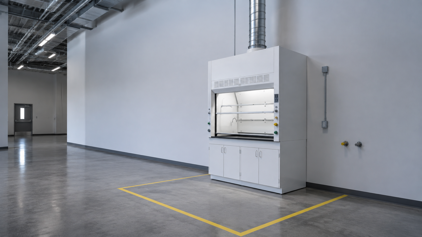
- Fume hood installation requirements are mostly room- and building-side requirements — the hood is a cabinet with hookups; placement, clearances, utilities, ductwork, makeup air and acceptance decide success.
- Treat guidance numbers as attributed guidance, not code — clearances (Esco), the 7–10-day timeline (Genie) and delivery dimensions/cost context (Lab Design News) are manufacturer or planner figures; check your model’s manual and local authority.
- Know which project you are on before you start — replacing a hood on existing services is a mechanical install; a first hood or an added hood is a building project with new duct, fan, supply-air changes, permits and engineering sign-offs.
- Plan the acceptance gate when you order, not after install — as-installed ASHRAE 110 testing, face velocity verified at the sash, an airflow monitor on the new-hood PO and the turnover document pack define “done.”
- After sign-off, the hood moves to periodic inspection — this guide hands over at acceptance; post-commissioning checks belong to the fume hood inspection checklist article.
Most pages about fume hood installation requirements describe uncrating a cabinet and connecting its services. The requirements that decide whether the project succeeds sit in the room and the building around that cabinet: where the hood can stand, what clearance it needs from traffic and walls, what the work surface must carry, which utility stub-ins must exist before delivery, how the exhaust duct reaches the roof, where replacement air comes from, and what acceptance testing must prove before sign-off.
This guide turns that requirement set into a checklist you can run from room planning to acceptance. It keeps attributed manufacturer and planner guidance separate from standards-derived obligations, labels every number with its source, and ends with the control-point checklist that defines when an installation is ready to hand over. Replacement installs and first-time building projects follow different paths; the first module tells you which one you are on.
Fume Hood Installation Requirements: Start with the Room and the Building
Before you compare quotes or book a delivery, settle the frame this guide uses: a fume hood is a cabinet that exhausts air, and the requirements that decide whether it works correctly belong to the room and the building around it.
The Hood Is the Simple Part: A Metal Box with Hookups
Lab planners make this point bluntly: a fume hood is essentially a metal box with hookups, and almost everything that makes it perform sits on the buyer’s side of the interface. The Lab Design News planning column “There Is No Easy Button for Adding a Fume Hood to a Lab” argues that the cabinet arrives ready, while the room provides the location, the structure, the utilities, the exhaust path and the supply air that turn it into a working ventilation device.
That split of responsibility shapes every checklist in this guide. A hood manufacturer validates the cabinet; your project must validate everything attached to it. When a location, duct run or makeup-air condition is missing or marginal, the hood does not compensate — it simply underperforms or fails the acceptance checks that come at the end.
First Decision: Which Project Track Are You On?
Two project tracks carry very different workloads. Track A replaces or relocates a hood where the duct, exhaust fan and utilities already exist; dealer and installer guides such as LOC Scientific’s five-step walkthrough (location, ductwork, electrical, securing and sealing, then testing) describe it as a mechanical install with a defined sequence. Track B installs a first hood or adds one where those services do not exist; the same planning guidance treats it as a building project that adds a vertical duct to the roof, an exhaust fan and supply-air modifications.
Choose your track by asking one question: is there an exhaust connection, duct path and fan capacity already sized to serve this hood, and are utilities present at the position? If the answer is not a clear yes, plan for Track B and involve a mechanical engineer early, because the later modules on ductwork, permits and makeup air then become mandatory reading rather than optional context.
The track decision also sets expectations. Track A work can follow a compact install-and-test schedule; Track B inherits building-level reviews that the acceptance module counts into your timeline. After this module you should be able to state which track your project is on and who owns the engineering review, because every later module assumes that answer.
Why Install Quality Is a Room- and Building-Level Issue
A hood does not install in isolation. Its exhaust pulls air out of the room, and the room’s supply system must return that air for the sash airflow to hold; the Makeup Air and Room Balance module carries the full mechanism and its institutional framing, so this section only flags the reason room planning comes first. Get the balance wrong and the problem surfaces at the sash opening — which is why the checklist starts with where the hood can stand.
Decide your track now and name who coordinates installation with facilities and EHS before you order anything. The next module starts the requirements checklist where the room decides first: where the hood can stand and what clearance it needs.
Room Location and Clearance: Where Your Fume Hood Can Actually Go
Room layout settles a large share of installation success before a crate is opened. This module gives the siting principles, the clearance values to plan against with their sources, the environmental envelope most hoods expect, and the site assessment that turns them into a location decision.
Siting Principles: Away from Doors, Traffic, Windows and Drafts
Place the hood away from doors, high-traffic routes, windows and drafts. Air movement at the sash opening disturbs the inward airflow the hood depends on, so high-activity and drafty positions make a weak installation even with correct ductwork. Logistics and dealer checklists (CME Corp, LOC Scientific) both list these siting rules before any other step.
A common industry recommendation is to keep the hood at least ten feet, roughly 3 m, from exits or areas of frequent movement. Treat that distance as common guidance rather than a code mandate: different clearance numbers in the next table measure different objects, and this exit distance is not the same rule as the working clearance in front of the hood.
Clearance Planning Table by Object
| What it applies to | Recommended clearance | Source and status |
|---|---|---|
| Pedestrian route in front of the hood | ≥1.0 m | Esco Lifesciences, manufacturer guidance |
| Back and sides, for cleaning access | ≥30 cm | Esco Lifesciences, manufacturer guidance |
| Service access around the hood | ≥50 cm | Esco Lifesciences, manufacturer guidance |
| Between opposing hoods | >3 m | Esco Lifesciences, manufacturer guidance |
| From opposing walls or obstructions | ≥2 m | Esco Lifesciences, manufacturer guidance |
| From pillars | ≥30 cm | Esco Lifesciences, manufacturer guidance |
| Ductless hood: top of cabinet to ceiling | ≥30 cm (ductless units only) | Esco Lifesciences, manufacturer guidance |
| Distance from exits or high-traffic paths | ≥10 ft (≈3 m) | LOC Scientific / CME Corp guidance, common recommendation |
These values are Esco Lifesciences’ recommended clearances from its own installation guide, labeled here so you do not mistake them for a universal code list. Clearance rules vary by manufacturer, so check your model’s manual before fixing the layout. Each row measures a different object — exit distance, front walkway, cleaning gap, service gap, opposing-hood spacing — and the rows must stay separate; merging them creates one false rule no source supports.
Environmental Envelope and Overhead Space
Esco’s installation guide also specifies the operating envelope its equipment expects: indoor use, altitude up to 2,000 m, relative humidity 20–90%, and a room temperature of 18–30 °C with the laboratory held within ±2 °C. Present this as a typical manufacturer envelope rather than a universal requirement, and confirm the limits in the manual of the hood you selected.
Overhead space comes from a different planning source. Lab Design News planning guidance notes that the most common hood width is 6 ft and that 8–10 ft of clear overhead height is usually needed, with overhead infrastructure — conduit, ducts, lighting and smoke detectors — frequently requiring re-routing, and wall or floor items such as outlets, gas turrets and sinks often needing relocation. Those are planner observations about typical labs, so verify them against your measured room.
Site Assessment Checklist
Walk the intended position with this checklist before committing to delivery:
- Siting: no door, high-traffic path, window or supply diffuser discharging directly at the sash.
- Clearances: each row of the clearance table measured in the real room, object by object.
- Overhead: confirm 8–10 ft of clear height and list every overhead item that must move.
- Environment: the space is indoor and within the envelope your unit’s manual states.
- Floor: level and rated for the unit’s weight (detailed in the delivery module).
- Utilities: electrical, water/drain and gas can reach the position (detailed in the utilities module).
When the site assessment is complete you can mark every clearance row against the measured room, confirm the environmental and overhead conditions, and decide whether the intended location passes before you spend on delivery. If any row fails, relocate or redesign the position now, because later modules assume the room layout is settled.
Delivery Dimensions and Site Access: Checking the Route Before the Hood Arrives
A fume hood arrives as a large one-piece unit, and the path to its final position must be proven before the truck does. This module covers the dimensions to expect, the route and floor checks, the rigging reality, and the receiving inspection that protects your claim if something arrives damaged.
What Arrives: One-Piece Dimensions
Hoods typically ship assembled rather than as flat parts. Lab Design News planning guidance describes a common delivery size of about 6 ft wide and up to roughly 3.5 ft deep, arriving as one piece, with doorways and elevators checked in advance. That is a planner’s description of typical units, not a specification — pull the verified drawings, including crate dimensions, for your exact model.
The numbers matter for a second reason: the crate adds height and depth to the cabinet dimensions, so a unit that fits the room on paper can still fail the corridor or elevator. Obtain the shipping dimensions from the manufacturer early, measure the route against them, and repeat the check for every swing and turn, not just the widest door.
Path Check: Doorways, Elevators, Corridors, Floor Load and Levelness
Work through the route from the receiving dock to the final position with these checks:
- Door and elevator openings: width, height, and which way the door swings.
- Corridor turns and landings: a long unit needs swing room at each corner.
- Elevator and floor capacity: compare rated load against the unit’s shipping weight.
- Floor levelness: a level floor simplifies both moving and the cabinet leveling that comes later.
CME Corp’s logistics checklist flags floor levelness and load capacity as pre-install items, and its trade-coordination guidance schedules HVAC and electrical crews around the move. Confirm the route during site assessment, not on delivery day, and reserve building access so the move does not compete with ongoing lab work.
Rigging Reality: One Project’s Numbers
One real logistics example shows what heavy moves involve. CME Corp describes a City of Hope project in which thirteen hoods of roughly 1,000 lb each were moved through doorways with pallet jacks by a team of nine people in about four hours. Read that as one project’s numbers, not a template: effort scales with unit weight, route turns and how many people the mover assigns.
Plan who does the rigging before the truck arrives. The installing vendor, facilities staff or a professional moving crew are all possible owners, and the choice depends on unit weight, door and elevator sizes, and how far the route runs. For unusually heavy or wide units, confirm the lifting plan — including any crane or special access — in writing ahead of delivery.
Receiving Inspection Before Uncrating
Make the receiving check a named step with a named owner:
- Inspect the crate and packaging for visible damage before signing the delivery receipt.
- Verify the model and configuration against the purchase order: width, sash type, accessories and service layout.
- Note any damage or missing parts immediately and file the claim with the carrier and supplier.
- Agree a staging point close to the final position so install day starts from the right spot.
After this module you can confirm the route, floor and rigging plan before the truck arrives, and you can name who owns the receiving inspection on delivery day. The next stage of the checklist covers what must be ready under and around the hood once it is in the room: the work surface, the base cabinet and the physical installation sequence.
Work Surface, Base Cabinet and Physical Installation: Preparing Install Day
Once the hood can reach its position, the work surface and base cabinet decide how it sits, and the physical steps that follow decide how well it is sealed into the room. This module prepares the surface, walks a representative installation sequence, marks where the manufacturer’s manual takes over, and flags the special installs that change the plan.
Base Cabinet and Work Surface Preparation
Verify before install day that the base cabinet and work surface can carry the hood you selected. Dealer guidance from LOC Scientific directs checking the work surface and base for weight and height compatibility with the unit, because a benchtop hood’s footprint and weight must be supported across its full bearing area rather than left to a surface that was never rated for it.
The worked sequence in Specialty Solutions’ guide, written around a Labconco Protector Extreme, is representative: level the base cabinet with its leveling feet first, set the epoxy work surface on top with an optional bead of RTV sealant underneath, then seat the hood so its rear angle sits flush against the back edge, leaving a front overhang that feeds airflow to the baffle slots. Those steps belong to that model’s example; your unit’s manual defines the exact hardware and sealant choices.
Decide before delivery whether the existing work surface and base cabinet pass the weight, height and leveling check or must be replaced or reinforced, and schedule that work ahead of install day so the installers arrive to a ready surface.
Setting the Hood: Lift Points, Sash and Sealing
Unpack the hood near its final position and lift it by the side rails and the back panel only — never by the front airfoil, which is not a lifting point. Specialty Solutions’ installer walkthrough is explicit on this, and the same source treats the move as a planned lift with enough people or rigging rather than an improvised carry.
Check the sash travels smoothly across its full range, and install the baffles according to the model before the unit is fully dressed. Seat the hood as the surface step described, then seal the liner-to-countertop joints so spills cannot collect underneath the working area; the exhaust collar connection and its sealing belong to the ductwork stage later in this guide.
Assign the physical install to a named owner — the supplying vendor’s installer, an authorized dealer crew or your facilities team — and confirm that owner holds the manual for your exact unit before scheduling. The sequence above is representative; the manual governs the details.
The OEM Manual Governs the Physical Procedure
Treat the manufacturer’s fume hood installation manual as the final authority for the physical steps on your specific unit — lifting points, sash hardware, baffle arrangement, sealants and torque values differ by model, and this guide is the planning and checklist layer, not a manual replacement. Searchers who want the actual procedure will be pointed to gated manual PDFs on manufacturer sites; this page deliberately stays at the level of what to plan and verify.
If anything in your manual conflicts with a general step in this guide, the manual wins, and the manual should sit with the install crew on site rather than in a drawer. Do not improvise a connection the manual does not show, and do not let a general guide substitute for the model-specific document.
Special Installs: Walk-In Floor-Mounted and Ducted vs Ductless
Walk-in and floor-mounted units replace the benchtop story entirely. XICHENG’s walk-in floor-mounted fume hood product page describes a floor-mounted, ducted enclosure with a full-height chamber and a floor-level or low-threshold access path; for that family the page directs confirming finished-floor elevation, level and load capacity, joints and coatings, and any embedded utilities before the hood is set, keeping anchors clear of structural conflicts and concealed services, supporting ductwork so its weight is never transferred to the hood, and planning any sectional delivery before manufacture rather than improvising it on site. Those points are product-page framing for that equipment line, verified from the page, not a universal code list.
The second fork changes how much of this guide is mandatory. Ducted hoods discharge through a building exhaust system, so they add the duct and roof-fan work the next modules describe; ductless units pass air through filters and return it to the room, removing the roof duct but adding filter-cabinet planning in the lab — the earlier clearance table already carries the ≥30 cm ceiling gap Esco recommends above a ductless cabinet. The full ducted vs ductless fume hood comparison covers the differences; here they matter because they decide which room-side conditions your project must create.
After this module you can confirm the work surface and base are ready or scheduled, name who runs the physical install with the OEM manual in hand, and flag whether a walk-in or ductless unit redirects your plan — settle those three before utilities and ductwork decisions lock in.
Electrical, Plumbing and Gas: The Utility Stub-Ins to Provision Before Delivery
With the surface and install plan fixed, utilities are the last set of conditions that must exist before the hood arrives. This module covers the electrical connection, water and drain, and gas or service fixtures, then the coordination that turns stub-ins into a schedule.
Electrical: Licensed Work, Nameplate and Dedicated Circuits
Electrical connection is licensed trade work performed to local codes, and the install guides agree on it: LOC Scientific, CME Corp and Specialty Solutions each route the wiring through a licensed electrician rather than a general installer. Plan for that trade to be scheduled, not improvised on install day.
The connection points come from the unit itself. The hood’s nameplate states its electrical specification, and the internal junction box is where the supply connects; auxiliary features such as lights, alarms, auto-sash and powered service fixtures need wiring planned in the same pass, and hard-wired service fixtures or GFCI outlets require a dedicated circuit. Specialty Solutions documents the nameplate-to-junction-box path in its worked install, and LOC Scientific’s guide flags the auxiliary-load wiring.
Confirm the circuit provisioning — voltage, phase and breaker capacity against the nameplate — and reserve the licensed electrician’s slot before delivery, so install day is not waiting on electrical work that should have been a pre-install item.
Water, Drain and Gas: Routing to the Hood Top
Plumbing and gas follow the same planning pattern: the unit defines the connection points, and the building must reach them. In Specialty Solutions’ worked example, a cup sink ties to a laboratory drain or a waste container, service fixtures connect at the unit’s knockout locations, and internal piping routes to the top of the hood where the building services tie in — so the building-side stub-ins must be positioned to meet the hood’s layout rather than the reverse.
Treat this as planning-level description, not plumbing instruction. Water, drain and gas connections are qualified trade work, and CME Corp’s checklist verifies utility connections against the manufacturer’s specifications before install. Local codes govern the trade work itself; this guide only tells you what must be waiting at the position.
Stub-In Coordination: Locate Before Delivery
Locate every utility stub-in before the hood is delivered, because moving a stub after the unit is seated is expensive and slow. The list is short: the electrical circuit at the junction-box position, the water supply and drain for a cup sink if fitted, gas at the fixture knockout if used, and any alarm or data wiring the configuration needs.
Coordinate the trades — electrical, plumbing and, where the exhaust side needs it, HVAC — into one install window, as CME Corp’s logistics checklist schedules trade work around the move. Write the stub-in locations and connection map down for install day and for the commissioning that follows, so the acceptance stage later in this guide can verify each service against the plan.
After this module, decide the stub-in and trade map now: confirm every utility stub-in is located and scheduled before delivery and name the trades responsible for each connection, so the installation sequence is not blocked by missing services when the hood arrives.
Ductwork, Exhaust and the Remote Blower: Engineering Inputs Your Install Needs
The room layout, surface and utilities are ready; the exhaust side now decides whether the hood actually moves air. This module covers the duct collar connection, the vertical duct decision, the information an engineer needs to size a remote blower, and the stack and pressure notes that shape the design.
Duct Collar Connection: Alignment and Sealing
The hood meets the exhaust system at its exhaust collar, and that joint has to be right. Installer and logistics guidance from Specialty Solutions and CME Corp both treat the duct-to-collar connection as an alignment-and-sealing step: the duct aligns with the collar before it is fastened, and the joint is sealed so it cannot leak air. A leaking or misaligned joint wastes exhaust volume and skews the airflow balance the commissioning stage will measure.
Sealant choice is part of the same step. LOC Scientific’s guide cautions that the sealant must be compatible with the duct material and the chemicals the hood exhausts, and CME Corp’s checklist verifies the duct-to-collar seal as a named inspection point. Keep the joint accessible for that inspection instead of burying it behind cladding.
The Vertical Duct Decision: New Run or Existing Capacity
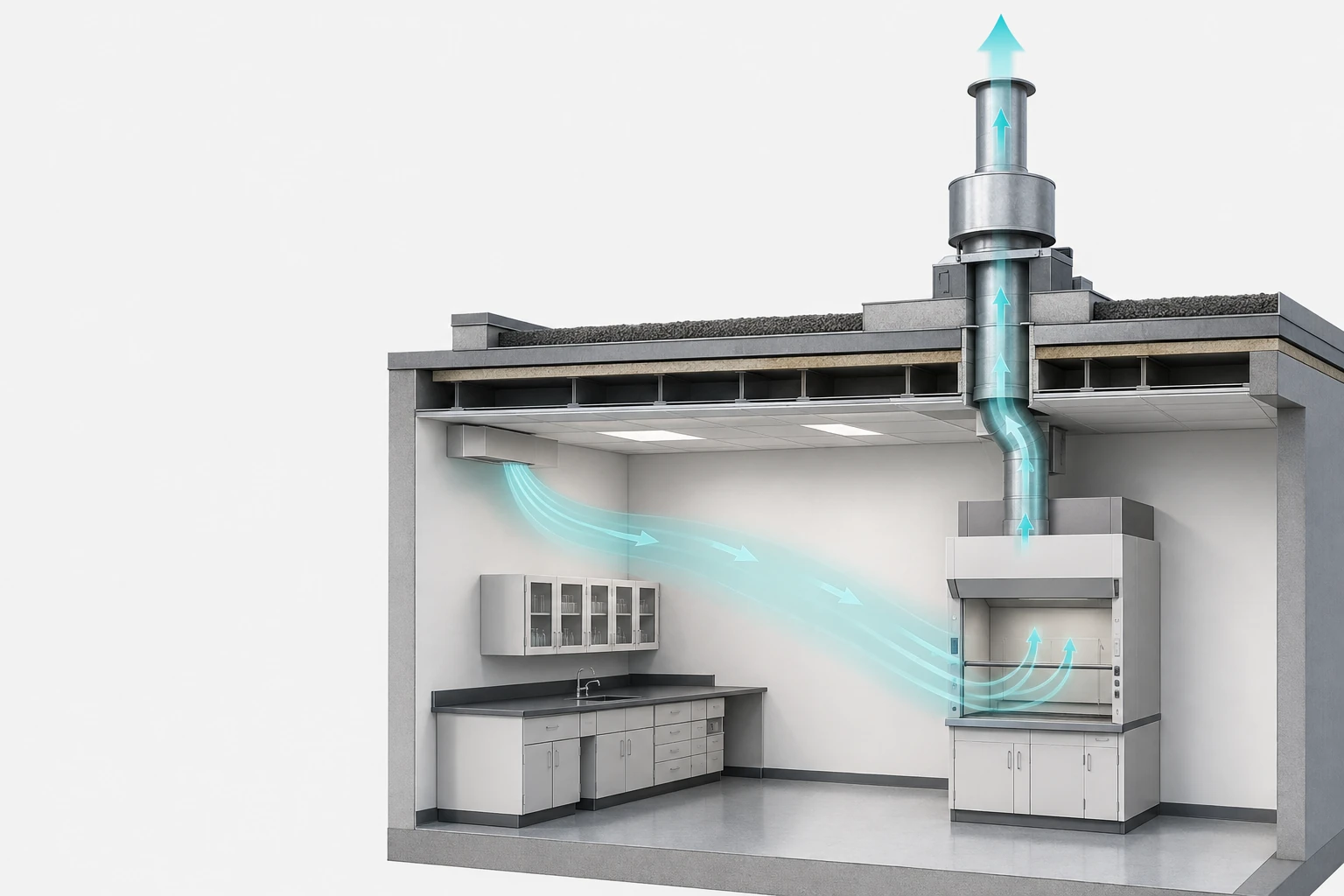
Adding a hood to a lab that has no exhaust for it usually means a new vertical duct from the hood top to a roof exhaust fan. That is the Lab Design News planner framing: a first-time installation means ductwork plus an exhaust fan plus supply-air modifications, because the building side does not exist yet. Treat that as planning guidance for typical buildings, not a universal design rule.
Where an existing lab exhaust system is in place, the same planner guidance directs that a mechanical engineer analyze whether that system can carry the added load before anyone orders a hood. The analysis decides between connecting to the existing duct and running a new one, and it belongs before the purchase order — an underpowered shared system drags every hood on it.
Remote Blower Sizing: The Information Card
Remote blower selection runs on inputs the planner can assemble without doing the calculation. Specialty Solutions’ installer guide lists what an HVAC designer needs: the duct diameter, the total run length to the roof, the number of 90-degree and 45-degree elbows in the path, and the duct material — coated steel, fiberglass-reinforced plastic (FRP) or PVC — chosen for the chemicals being exhausted.
Your job is to fill the card, not to solve it. Collecting duct diameter, run length, elbow count and material gives the engineer what they need to select the blower; turning those inputs into a fan size and duct size is HVAC design work that belongs to the engineer and the project’s design references. Keep the information card complete so the engineer never has to guess the inputs.
Stack and Pressure Planning Notes
Two planning notes from the standards reading deserve a place in this module. As quoted in Laboratory Design’s 2017 guide to fume hood codes and standards, exhaust should discharge vertically, at least 10 ft above the adjacent roof line, and be located to avoid re-entrainment into building intakes; hood exhaust must not be recirculated; and chemical areas are held at negative pressure to occupied areas. That is a 2017 reading of the standards, so verify each point against the current edition before your design relies on it.
Stack design stays with the HVAC engineer; the checklist item here exists only so the requirement is not forgotten at the roof. If the exhaust plan lacks a vertical discharge above the roof line or allows recirculation, stop the design review and send it back before ordering equipment.
After this module you know whether your install needs a new vertical duct or a capacity analysis of the existing system, and you can hand the HVAC designer a complete blower-sizing input card — duct diameter, run length, elbow count and material — before any fan is ordered.
Standards, Permits and Engineering Sign-Offs: The Requirements Layer Around Your Installation
With the physical and exhaust plan fixed, this module maps the obligations and approvals the project sits on: which standards attach to installation and acceptance, which permits the work triggers, and which engineering sign-offs protect the building.
Standards Quick Reference for Installation and Acceptance
| Obligation (as quoted) | Source standard | Where it attaches |
|---|---|---|
| Evaluate the hood at installation, at least every three months thereafter, and after any change; continuous monitoring devices | OSHA 1910.1450 (laboratory standard context) | Install and ongoing operation |
| New and remodeled hoods shall be equipped with a flow-measuring device; annual testing | ANSI/AIHA Z9.5 | New/remodeled installs; annual |
| No exhaust recirculation; chemical areas at negative pressure; inspection and testing at installation and at least annually; hood sign or log recording interval, last inspection date, average face velocity, fan location and inspector | NFPA 45 | Install and annual |
| Face-velocity acceptability guidance for hood performance | SEFA 1.2 (context) | Acceptance discussion |
Every row is quoted from Laboratory Design’s 2017 guide to fume hood codes and standards, an industry-media reading of the standards rather than the standards themselves. Verify each obligation against the current edition of the applicable standard and your local authority before treating it as binding, and do not read this table as a legal summary.
The numeric side of face velocity — what the ranges mean, how a setpoint is set, and how a reading is accepted — belongs to the fume hood face velocity requirements guide, which owns that semantics. This page only lists the obligations; that guide explains the numbers.
Permits and Approvals: Mechanical Permit and the Local Authority
Run the approvals as a checklist with a named owner per row. The framing is the Lab Design News planner position for the US market; confirm each item with your local authority having jurisdiction rather than assuming a national rule.
| Permit / approval item | What it covers | Owner / role | When |
|---|---|---|---|
| Mechanical permit | Required for nearly every hood installation, including one connecting to an existing exhaust system | Project / permit applicant | Before installation begins |
| Architect or structural engineer | Larger modifications: structural changes, duct routing through floors or walls, roof work | Design professional, per local rules | During design |
Add permit lead time to the project schedule, because it regularly outlasts the install estimate. Keep the permit file with the other installation documents the acceptance module collects, and check with the authority having jurisdiction early.
Engineering Sign-Off Chain: Roof, Structure and Capacity
Each engineering sign-off has a named owner and a place in the schedule before the hood is ordered (planner guidance: Lab Design News).
| Engineering item | What it verifies | Owner / role | When |
|---|---|---|---|
| Existing-system capacity analysis | Whether an existing exhaust system can carry an added hood’s load | Mechanical engineer | Before the hood is ordered |
| Rooftop fan structural review | Whether the roof can take the fan’s weight | Structural engineer | Before installation |
| Roof penetration reinforcement and waterproofing | Penetration detailed in the design, not improvised on site | Structural engineer / roofing contractor | During design, before installation |
| Install coordination | Facilities and EHS involved in planning the installation | Project / facilities | Before installation |
After this module you can list the standards obligations that attach at installation versus ongoing, name the permits to pull with your local authority confirmed, and identify the engineers who must sign off before installation begins.
Makeup Air and Room Balance: Supplying What the Exhaust Removes
The exhaust side only works when the room gives air back. This module explains the makeup-air mechanism, why a shortage reaches beyond one hood, and the balance checks to put on the commissioning list.
The Mechanism: Exhaust Removes Air, Makeup Must Replace It
A hood’s exhaust continuously removes room air, and that air has to be replaced by the supply system. Lab planners describe the relationship in plain terms: the hood moves air out, and the building’s supply air must keep pace, or the room cannot deliver the airflow the hood was designed around. No pressure number is needed to hold this point — the requirement is that supply capacity matches exhaust volume for the space.
Makeup air is therefore part of the ventilation design, not an afterthought. When supply falls short, the room finds the air from wherever it can, and the results show up at the sash openings as weaker inflow. Confirm who owns the supply-side number for your room before the hood order, and put that person’s name in the project file.
Impact Beyond One Hood: Room and Building Balance
A supply shortage rarely stays local. Cornell University’s EHS laboratory safety manual warns that an improperly installed hood can disrupt airflow in the room and degrade the performance of other hoods and of the building’s ventilation system; that statement is one institution’s practice, but the mechanism generalizes — hoods in one room share the same air, so a shortage for one is a shortage for all.
The practical consequence is coordination. First-time and add-on installations change the supply side as well as the exhaust side, so the project plan should bring facilities and EHS in before the install rather than after a balance problem appears. If your building cannot supply the air, the correct move is to fix the supply design before the hood arrives.
Balance Checklist: What to Verify at Commissioning
Put these checks on the commissioning list with named owners:
- Supply capacity confirmed against total exhaust for the room, including other hoods.
- Supply and exhaust systems coordinated so airflow changes do not fight each other.
- Room balance verified during commissioning, before acceptance sign-off.
- Supply-air presence verified at commissioning: the supply damper responds and delivered airflow matches the design while the hood exhausts, before the room-balance sign-off.
- Makeup-air and duct design calculations assigned to the HVAC engineer — this checklist makes sure the owner exists, it does not replace the calculation.
No pressure value is required to run these checks; the numbers belong to your project’s design and to the acceptance stage that follows.
After this module you can name who owns the makeup-air capacity for your room and add the balance checks to the commissioning list — the next module turns those checks into the acceptance gate and the final delivery checklist.
What Fume Hood Installation Requirements Should Acceptance Testing Verify?
Acceptance testing answers the question the whole checklist has been building toward: does this hood, as installed in this room with these services, actually perform? The tests below verify the installed system, the documentation proves the work, and the sign-off decides whether the hood is released for use.
As-Installed Acceptance Tests
The central acceptance deliverable is as-installed testing of the installed hood and its connected system. Institutional practice — Cornell EHS frames commissioning this way — treats as-installed ASHRAE 110 testing, turnover documentation and asset registration as the commissioning deliverables of a new hood. The method detail, test menu and procedure for ASHRAE 110 belong to the ASHRAE 110 fume hood testing guide; here it is a named deliverable your project must schedule before sign-off.
Face velocity is part of the same gate: the hood is balanced to the specified setpoint and the result is verified at the sash opening with an anemometer, not assumed from the blower setting. What the setpoint means, how the ranges are read and how a value is accepted are covered by the fume hood face velocity requirements guide, which owns that semantics; this checklist records that the verification happened at the sash.
Airflow Monitor on the New-Hood PO
Put the airflow monitor on the purchase order now rather than discovering its absence during commissioning. The 2017 standards reading used throughout this guide quotes ANSI/AIHA Z9.5 and NFPA 45 as requiring a flow-measuring device on new and remodeled hoods, with annual testing after that; verify the requirement against the current edition of each standard before treating it as binding for your project.
A monitor is an aid to verification, not a substitute for it. XICHENG’s fume hood airflow monitor product page is explicit that the display does not create the measurements and does not regulate exhaust airflow on its own, and that it is ready for use only after the installed system passes its functional check against the commissioned measurement. Order the monitor with the hood, wire it during installation, and check it in the same acceptance pass.
Acceptance Sign-Off Checklist
Run this sign-off list with named owners before the hood is released:
| Check | What it verifies | Owner |
|---|---|---|
| As-installed ASHRAE 110 testing completed | Containment of the installed system | Qualified tester / commissioning party |
| Face velocity verified at the sash opening | Balance to the specified setpoint | Qualified tester / commissioning party |
| Airflow monitor installed and functional | Continuous airflow indication | Installer + commissioning party |
| As-installed record and turnover documentation | What was built and tested | Project / facilities |
| Asset registration completed | The hood is on the lab’s equipment records | Facilities / EHS |
| Operator training recorded | Users can operate and respond to alarms | Project / EHS |
| Hood sign or log in place | Interval, last inspection, fan location, inspector | EHS / facilities |
Documentation is part of the deliverable, not paperwork after the fact. Keep the as-installed record, test results, permits, manual and warranty in the file the institution keeps for the hood, and record the training before first use. Once acceptance is signed, the hood enters the periodic inspection cycle: post-commissioning checks move to the fume hood inspection checklist guide, which owns daily, annual and return-to-service inspection semantics.
Timeline Expectations and Pitfalls
A realistic schedule starts from the manufacturer’s estimate and adds project reality. Genie Scientific, a hood manufacturer, estimates a standard installation at roughly 7–10 working days end to end: site assessment 1–2 days, installation 3–5 days, testing and calibration 1–2 days, and final inspection and certification about 1 day. That is one manufacturer’s estimate for a standard hood, not a promise and not a universal duration — custom work and retrofits take longer.
Plan against the failure modes the same sources flag. Common pitfalls are hood misalignment, undersized or blocked exhaust, unlicensed electrical or plumbing work, poor interior lighting, and compliance delays from permits; each maps to a checklist row in this guide — alignment to the physical install steps, exhaust to the duct and fan review, trades to the utilities module, lighting to the receiving check, and permits to the approvals module. If a pitfall shows up in your plan, the fix is the checklist row it maps to, scheduled before the stage that would suffer.
Your Fume Hood Installation Checklist: Control Points from Pre-Arrival to Acceptance Sign-Off
The whole guide collapses into three checklists you can run in order. Before the hood arrives: confirm the project track, the room location against the clearance table, the delivery route and floor, the work surface and base readiness, the utility stub-ins, the duct and fan inputs with an engineer, the permits and sign-offs, and the makeup-air owner. On install day: level the base, set the work surface, seat and seal the hood, connect and seal the duct collar, complete the utility tie-ins, and verify the sash and baffles. At acceptance: run the as-installed tests, verify face velocity at the sash, check the airflow monitor, complete the sign-off table above, and file the documentation.
Working the lists in order is what separates a controlled installation from a reactive one. Together, these fume hood installation requirements reduce to room and building readiness, a clean install sequence, and an acceptance gate nobody skips — and when your room passes all three stages, the next step is matching the checklist to an actual unit: compare laboratory fume hood systems against your utility, exhaust and control inputs with the XICHENG engineering team, and confirm the field scope in the quotation before you commit.
Frequently Asked Questions
What counts as a fume hood installation requirement?
A fume hood installation requirement is any condition the room and building must provide before the hood can perform: location and clearances, work surface and base readiness, utility stub-ins, ductwork and exhaust capacity, makeup air, and the acceptance checks that prove the installed system works. The hood cabinet is only part of the picture.
Do I need a permit to install a fume hood?
Planner guidance for the US market says almost every fume hood installation — even one connecting to an existing exhaust system — requires a mechanical permit. Confirm the requirement with your local authority having jurisdiction, because local rules decide, and larger structural or roof modifications can add an architect or structural engineer.
How much clearance does a fume hood need?
Clearance depends on the object, and the values stay separate: the room-location table in this guide lists Esco’s recommended clearances — at least 1.0 m of pedestrian route in front, 30 cm behind and at the sides for cleaning, 50 cm for service, more than 3 m between opposing hoods and 2 m from opposing walls — while keeping a hood at least ten feet, about 3 m, from exits is common guidance from other sources rather than a code mandate. Check your model’s manual before fixing the layout.
Can I add a fume hood to an existing lab exhaust system?
Usually yes, but only after a mechanical engineer analyzes whether the existing system can carry the added load. The planner guidance behind this point treats the capacity analysis as a required step before the hood is ordered, because an underpowered shared system affects every hood connected to it.
How long does a fume hood installation take?
Genie Scientific estimates a standard installation at roughly 7–10 working days: assessment 1–2 days, installation 3–5 days, testing and calibration 1–2 days, and final inspection about 1 day. That is a manufacturer estimate for a standard hood, not a promise; custom work and retrofits take longer, and permits add lead time.
Does a new fume hood need an airflow monitor?
Under the 2017 standards reading quoted in this guide, ANSI/AIHA Z9.5 and NFPA 45 require a flow-measuring device on new and remodeled hoods, so most new installations include one. Verify that requirement against the current edition of the standards, and remember the monitor supports verification — it does not replace the acceptance measurement of face velocity at the sash opening.
Leave a Reply