




Key Takeaways
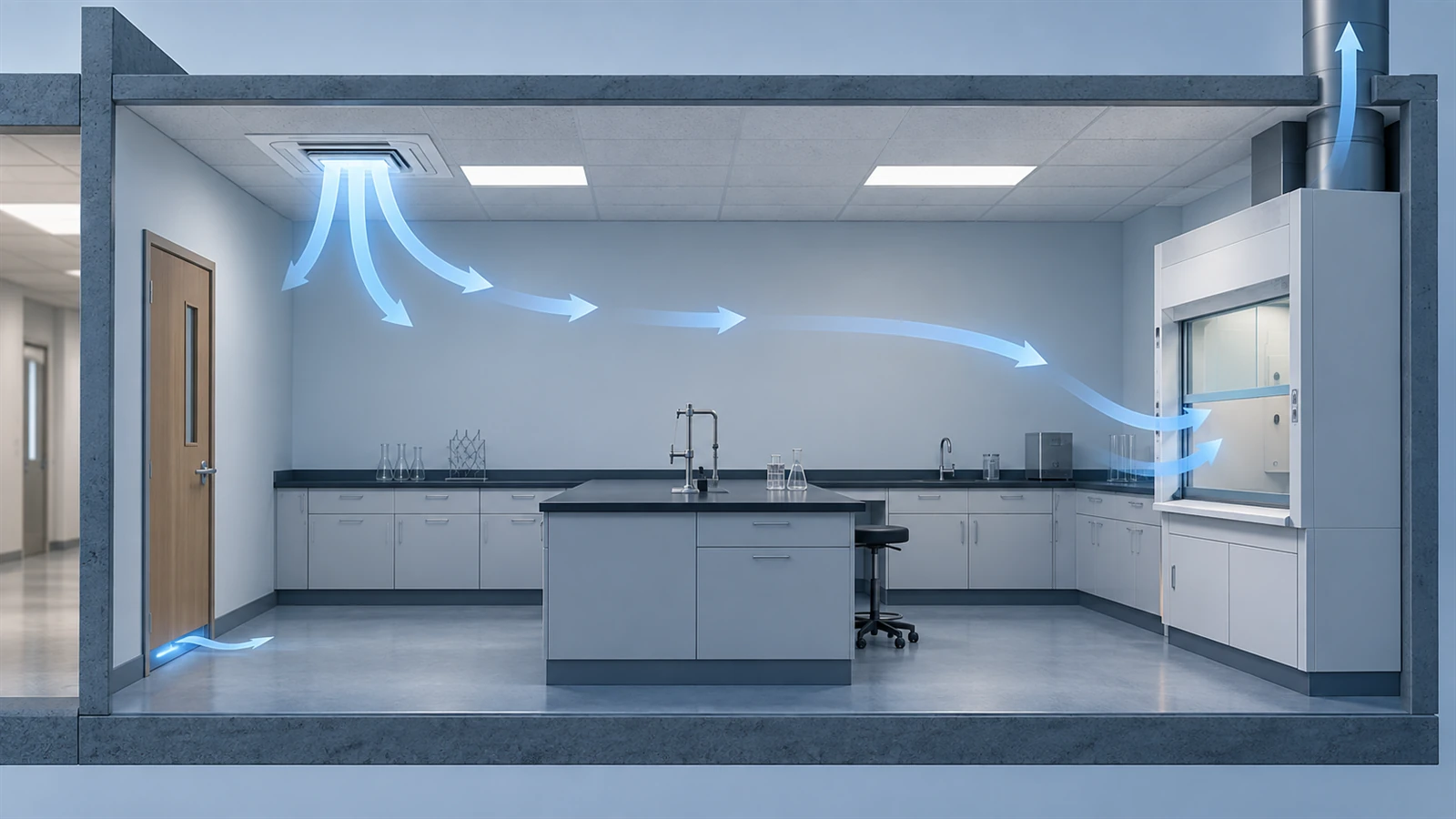
- Makeup air is the supply air a lab takes in to replace what its hoods exhaust, and fume hood makeup air requirements are set by volume, path and room pressure together. The volume follows from total hood exhaust minus the offset your pressure target allows.
- No universal legal percentage governs makeup air volume. Two independent university design guidelines use 90% of exhaust as an institutional design value, not a code requirement.
- Room pressure is the first number to settle. Setting targets for chemical labs are commonly quoted around 0.01 in. w.c. as an engineering implementation figure, and a differential that is too large makes doors hard to open and causes whistling at gaps.
- Makeup air has to arrive without disturbing the hood. The air speed in the hood face area must not exceed 20–25 fpm, measured with hood exhaust off, and the supply diffuser jet has to stay below half the capture velocity.
- Commission the room side, not the hood alone. Pressure differential, diffuser jet speed, hood-face room air speed, air balance and door-open behavior belong on the acceptance list.
Laboratory makeup air differs from residential practice, and the difference decides how you size it. If you add a hood to a working lab, you are not sizing a kitchen exhaust: you are balancing a room whose pressure, air path and exhaust volume all have to hold at once. Kitchen range hood makeup air rules, including the IRC M1503.4 provisions you will find cited in residential work, do not apply to a laboratory fume hood. The steps below follow fume hood makeup air requirements in the order a retrofit decision actually gets made.
Direct answer. Fume hood makeup air requirements can be reduced to one relationship and three settings. The makeup air volume for a room equals the total exhaust from that room’s hoods minus the airflow offset the pressure target allows, and it must also satisfy the room cooling load, whichever is larger. The makeup air path must reach the room without crossing the hood face, and the room pressure differential must be a value your doors can tolerate.
Fume Hood Makeup Air Requirements: Direct Answer and Scope
What Fume Hood Makeup Air Requirements Cover and What They Leave to Others
They set three things and leave two to other documents. Makeup air volume is a material balance question: the air leaving through the hoods has to be replaced by air entering the room, minus whatever offset holds the pressure. Makeup air path is a geometry question: where the supply enters relative to the hood. Room pressure is the result of both, and it is what the rest of the building feels.
What they leave alone matters just as much. Face velocity requirements belong to the hood, not to the room. Duct sizing and fan selection belong to the exhaust system downstream of the hood. Hood placement relative to doors, aisles and diffusers is a layout question with its own page.
That split explains why a search for one number, a makeup air percentage or a CFM figure, comes back with conflicting answers. Each answer is answering a different part of the problem. You can decide which of the three settings your project still has open before you ask anyone for a quote.
Which Documents Govern Makeup Air in a Laboratory
| Document | Type | What it addresses for makeup air |
|---|---|---|
| OSHA 29 CFR 1910.1450 | Federal regulation | Requires engineering controls, including fume hoods kept in working order. It sets no airflow value. Its Appendix A guidance, which is non-mandatory, places engineering controls first in the hierarchy of controls. |
| NIH ORS Design Requirements Manual | Government design manual | Directed airflow from corridor into each lab, offset magnitudes, pressure limits, airflow tracking response, and the rule that makeup air must satisfy cooling load and exhaust demand, whichever is larger. |
| Stanford and Drexel design guidelines | University design guidelines | The institutional design value of 90% of exhaust volume, plus the requirement that makeup air hold negative pressure without producing disruptive airflow patterns. |
| CDC infection control guidance | Government health guidance | Pressure differential magnitude of greater than ±2.5 Pa, stated for healthcare settings. |
| EPA 1978 laboratory fume hood standards | Government technical standards | Air speed from makeup air in the hood face area, capped at 20–25 fpm and measured with hood exhaust off. |
| UKY fume hood building design criteria | University EHS criteria | Supply diffuser jet velocity, held below half the capture velocity of the hood. |
The table also shows the shape of the answer. A regulation tells you that you must have ventilation and that the hood must work. A design manual tells you how to build one. A university guideline tells you what that institution accepts. Your project specification is what turns any of them into a requirement you can be held to.
Treating those types as interchangeable causes predictable failures. Adopt a university design guideline as if it were an acceptance limit and a contractor can be failed on a number the project never required. Quote a standard by number while treating its provisions as known, and the specification ends up asserting something no one in the project has read. Leave the type of each requirement unstated, and disputes land on interpretation rather than on a document.
State which document each makeup air requirement comes from, and by what right it applies to your project, before the installation is priced. You can decide which requirements are enforceable and which are background, and you can tell a bidder exactly which line in the specification they are bidding against.
Scope and Audience: Retrofits, Renovations and New Installations
Adding a hood to a lab that already exists, rather than starting from an empty room, is the situation these steps are built around. Three features separate a retrofit from a clean-sheet design.
Existing exhaust and supply capacity is a fixed constraint, and the records for it are often incomplete. Room geometry and door locations are already decided, and the acceptance process may already have an owner.
Two consequences follow for how you read the rest of these steps. First, every rule here is a decision input, not a recipe: the numbers depend on your room’s leakage, your door operating force and your project specification. Second, the order matters more than any single value, because a makeup air volume that is correct on paper can still fail if the room cannot hold pressure or the supply air reaches the hood face too fast.
Building the answers to those three settings in order, and taking the measured values your installer reports as the record, is what lets you keep a working lab working. You can state your project’s makeup air volume, path and pressure target to a contractor once you have worked through the steps below.
How Much Makeup Air a Fume Hood Needs: Exhaust Volume and Supply Calculation
How Exhaust Volume Is Established for a Hood
Exhaust volume is the product of face velocity and the open area of the sash, and neither number belongs to the room. A hood exhausting 700 cfm and a hood exhausting 1,200 cfm can be the same cabinet at two sash positions, which is why an airflow figure quoted without a sash condition says almost nothing about the system behind it.
Two references carry the working assumptions. The face velocity requirement itself, and the working sash height your operators actually use, are both covered in the face velocity requirements and sash height pages. The starting point here is where they end: given an exhaust volume per hood, how much supply air does the room need. The airflow calculation method behind that first number is covered in its own right.
| Input | Where it comes from | Why it matters for makeup air |
|---|---|---|
| Face velocity at the working sash | Face velocity requirements page | Sets exhaust per hood at the operating position |
| Working sash height | Sash height page | Open area is height times width |
| Number of hoods in the room | Project equipment list | Exhaust is additive across the room |
| Simultaneous use assumption | Project policy or observed practice | Determines the room total, not the sum of every hood at full open |
Why Makeup Air Is Not a Fixed Percentage of Exhaust
Search results for fume hood makeup air requirements often produce a single percentage, and two different ones compete. One line of thinking says a room should be supplied with 100% fresh makeup air, meaning the supply is not recirculated from other spaces. The other says makeup air should be about 90% of exhaust volume. These are not the same statement, and treating them as rivals is what makes the topic confusing.
The 100% figure describes air quality: the supply has to be outdoor air, or at least air not carrying other spaces’ contaminants, rather than recirculated room air. The 90% figure describes quantity: a design value two separate university guidelines arrived at independently for how much supply volume a lab needs relative to its exhaust, namely Stanford’s laboratory standard and design guidelines and Drexel’s building system standards and design guide.
Both are institutional positions rather than legal requirements. No federal regulation sets a percentage, and no government design document sets one. What the government material does provide is a rule about how to treat the two demands on the supply system.
Makeup air volume has to satisfy the room cooling load and the exhaust demand, and the larger of the two governs. When exhaust exceeds what the cooling load requires, supply must be increased to cover the difference. That single rule replaces the search for a universal percentage: your percentage is an output of two calculations, not an input to them.
Sizing a Makeup Air System: The Six-Step Calculation Chain
The chain below is the working method for a retrofit. Each step produces one number you can put in a project document.
| Step | Input | Output |
|---|---|---|
| 1 | Face velocity and working sash height per hood | Exhaust volume per hood, in cfm |
| 2 | Hood count and a simultaneous use assumption | Room exhaust total, in cfm |
| 3 | Target room pressure differential and the room’s leakage behavior | Permitted supply-to-exhaust airflow offset, in cfm |
| 4 | Room exhaust total minus permitted offset | Makeup air volume required for the exhaust balance, in cfm |
| 5 | Room cooling load converted to supply volume | The larger of cooling-driven supply and exhaust-driven supply |
| 6 | Diffuser selection and its throw pattern | Whether the chosen supply can deliver that volume without disturbing the hood |
Steps 1 and 2 are the exhaust side and are covered in more detail where airflow calculation is discussed. Steps 3 and 4 depend on the pressure target, which is the next decision. Steps 5 and 6 are where makeup air volume stops being a pure balance question and becomes a mechanical one, and step 6 is where a correct volume can still fail in practice.
A note on where the offset assumption comes from: it belongs to the pressure decision, so the number you write into step 3 has to be reconciled with the pressure target you set in the next step. Do not let a contractor insert a percentage here in place of an offset expressed in cfm.
Simultaneous Use, Diversity and the Room Total
Room exhaust totals are usually lower than the arithmetic sum of every hood at full open, and the gap is the diversity assumption. Diversity is the fraction of installed hoods assumed to be operating at once. A teaching lab with eight hoods used in one scheduled session needs a different assumption than a research bay where two hoods run continuously.
Understating diversity understates the room exhaust total, and with it the makeup air volume the room is built to deliver. Overstating diversity moves the calculation the other way: the room is supplied for hoods that are rarely open together, which raises first cost and raises the supply volume that has to reach the hood face without disturbing it.
The two errors fail differently, which is why the assumption needs to be written down and checked. An understated assumption shows up when every hood is open at once and the room can no longer hold its target differential. An overstated one shows up as excess supply, with the room drifting toward positive and supply outlet velocities higher than the hoods tolerate.
Diversity is a project policy decision, and it belongs in writing before the calculation is run. A defensible assumption states the hood count, the assumed simultaneous fraction, and the operating condition of the remainder.
Gather these six inputs before you ask for a makeup air volume: hood count and model, working sash height, required face velocity, diversity assumption, target room pressure differential, and room cooling load. With them, you can determine the supply volume your project needs and see immediately whether the existing system has any capacity left to serve it.
Room Pressure and Leakage: What Makeup Air Must Hold
Why Room Pressure Is the First Quantitative Check
Room air balance in a laboratory is not a comfort measure; it is what keeps air moving from clean spaces toward the hood. The institutional standard is a lab held at negative pressure relative to its corridor, so that air flows from the corridor into the lab and not the other way. Government design material states that direction as a design requirement, and it treats the flow into each lab as a directed quantity rather than a byproduct of the supply and exhaust settings.
That direction is why makeup air volume and room pressure cannot be decided separately. Every cfm you remove from supply to deepen the negative pressure is a cfm that cabinet exhaust must pull through door gaps, wall penetrations and any other leakage path. If those paths cannot pass the airflow, the pressure you designed for simply does not appear.
The corollary matters for retrofits. A room’s leakage area is a physical property you inherit, and it sets the ceiling on how much offset a given pressure target will produce. You can choose a target, but the room decides what it costs in airflow. The VAV control dampers that hold the offset are a separate selection decision, and the article on airflow control strategy explains why the choice of control approach changes how the room behaves when a sash moves.
Design Target, Operating Reading and Acceptance Test: Three Different Numbers
Three numbers get confused constantly, and the confusion produces arguments during commissioning. A design target is what the engineer specifies. An operating reading is what the room actually holds with the ventilation running and the doors closed. An acceptance test is the measured value taken under defined conditions, on a defined instrument, and signed by a defined party.
| Quantity | Who sets it | When it is measured | What it decides |
|---|---|---|---|
| Design target | Project engineer, in the specification | Never measured; it is an instruction | The offset the control system is asked to hold |
| Operating reading | The room, moment to moment | Continuously, or on spot checks | Whether the system is holding what it was asked to hold |
| Acceptance test | Project specification and the authority having jurisdiction | Once, under stated conditions, at handover | Whether the installation is accepted and paid for |
Treating an operating reading as an acceptance test is the most common error, because a spot reading in a quiet room looks like a passing result. It is not the same measurement: acceptance conditions usually specify door position, exhaust operating state and instrument type, and those conditions change the number.
The Tradeoff Between Offset, Door Operability and Leakage Area
Offset is the deliberate difference between supply and exhaust airflow. It is the mechanism that creates the pressure difference, and it is not free. Government design material states the tradeoff directly: in a section on space pressurization, it notes that a differential greater than 25 Pa (0.1 in. w.g.) makes doors difficult to open and close and produces whistling at gaps. That is a defect condition, not a safety margin.
The same manual includes low-leakage space provisions that limit how much a control loop may offset one airflow against another, and the stated reason is door operability rather than airflow economics. Those particular figures are written for animal facility and other classified spaces, and the same clause states that it does not apply to chemical fume hoods, biological safety cabinets, canopy hoods or other safety equipment. The transferable content is the mechanism, not the number: an offset that is too large shows up at the door, and door force is a design constraint on your pressure target.
How much pressure a given offset produces depends on the room’s total leakage area. A tight room reaches a large differential from a small offset; a leaky room needs a large offset for the same reading, and may never get there. In engineering implementation terms, room pressure is a function of the airflow offset and the room’s total leakage area; that relationship is used in room pressurization control design and is not stated as a code requirement. The numbers belong to a specific room and are measured rather than assumed. Your next step is to ask what offset your pressure target actually requires in this room rather than accepting a percentage.
Pressure Measurement Points and Magnitudes
| Source and scope | Magnitude | Conditions and source type |
|---|---|---|
| Healthcare infection control guidance | Greater than ±2.5 Pa (0.01 in. w.g.) | Applies to healthcare settings. A chemistry laboratory sets its own target from its own basis rather than adopting this magnitude. |
| Clean and classified space design practice | 10 Pa for like-to-like, not below 7.5 Pa; 10–15 Pa between unlike spaces | Classified and clean spaces only, not a general chemistry lab |
| Commonly quoted negative pressure target for a chemical lab | Around 0.01 in. w.c. | An engineering implementation figure rather than a standard value. Confirm it against your room’s measured leakage and the door operating force before adopting it. |
| Door operability limit | Above 25 Pa (0.1 in. w.g.), doors become hard to operate and gaps whistle | An upper bound that makes the target a range, not a minimum to beat |
The clean and classified space row and the 25 Pa row come from the same section of the same institutional manual, and both sit in a clean and classified space context. Used in a chemical laboratory, the 25 Pa figure is a mechanism-level upper bound on how much differential a room can be asked to hold, not an acceptance limit to test against.
A pressure target written without a range is an incomplete specification. The useful form states a direction, a magnitude and an upper bound: for example, negative relative to the corridor, near 0.01 in. w.c., and below the value at which doors stop operating normally.
Special spaces may need the opposite direction of differential from the surrounding corridor, with their own magnitude. That is a property of the space classification, not a general lab requirement.
Fault Conditions: Direction, Response Time and What Must Not Reverse
Pressure control has to survive failures, and the acceptance criteria for that are stated in institutional design material. Airflow tracking must hold the pressure difference between adjacent spaces and must not allow the differential to remain outside its range for more than two minutes, adjustable. The same clause requires that the designed airflow direction must not reverse under fault conditions.
Read those two requirements as a single test: you are not only specifying a pressure, you are specifying how long the room may be wrong and which direction it may never go. A system that recovers eventually but reverses during the excursion fails the second requirement even though it passes the first.
The measured response is what proves the requirement. That is why commissioning includes forcing sash movement and observing recovery, and why the record has to name the instrument and the conditions. You can select the pressure target and the permissible recovery window for your project documents with these three elements in hand: direction, magnitude, and the time the room may spend outside its range.
Makeup air volume and pressure offset are locked together by that choice, so choose them in the same conversation.
Laboratory Makeup Air for Fume Hoods: Paths, Diffuser Velocity and Short-Circuiting
Where Makeup Air Enters: Two Institution-Level Rules
Makeup air has two requirements that pull in the same direction: it must arrive far enough from the hood that it does not push into the working opening, and it must not carry the room’s pressure the wrong way. University design guidelines state the first as a preference for introducing supply at the end of the room opposite the hood, and for routing the room’s airflow path so it avoids the hood position. A second independent guideline states the same condition: introducing makeup air must maintain the negative pressure and must not create disruptive airflow patterns.
Together those rules define the failure mode to design away from. Air that enters beside or in front of the hood arrives with its velocity still intact, crosses the face and disturbs the inflow at the working opening. Air that enters anywhere still has to leave, and the path it takes across the room is the path the contaminants would take in reverse.
| Rule | Practical meaning for a retrofit | How you verify it |
|---|---|---|
| Introduce supply opposite the hood | The existing diffuser may be on the wrong wall | Mark diffuser and hood positions on a plan before ordering |
| Route the airflow path away from the hood | Open doors and high-traffic aisles can create a path you did not design | Walk the room with a smoke source during commissioning |
| Maintain negative pressure while supplying | Adding supply without rebalancing exhaust can flip the room positive | Measure differential after supply is commissioned |
| Avoid disruptive airflow patterns | A supply diffuser aimed at the face is a disruption even at low volume | Check jet direction and throw during the acceptance test |
For a retrofit, the plan review is cheap and the correction is not. Moving a diffuser later means new ductwork inside a finished ceiling.
Diffuser Jet Velocity Against Capture Velocity
Diffuser jet velocity scales with supply volume and inversely with diffuser size, which is why the same room can fail at one diffuser selection and pass at another without any change to airflow. University EHS criteria put a limit on this directly: the air jet velocity from supply diffusers is to be less than half the capture velocity of the exhaust hood, and preferably less than one third.
Read that as a relationship rather than a number. The requirement is proportion, so it adapts to hoods with different capture velocities, and it tells you the direction of the fix when a room fails. Lower the jet velocity by enlarging the diffuser face, spreading the supply across more outlets, or directing the throw away from the working zone.
Low-velocity, large-face supply is also the mechanism that keeps supply air from arriving as a jet at all. Where a diffuser has to be positioned less ideally, the alternative stated in Stanford’s EHS laboratory design guidelines is to direct the airflow toward the ceiling so its energy dissipates before the air reaches the hood. That trades a velocity problem for a distance problem.
Makeup Air That Reaches the Hood Face: What the 20–25 fpm Limit Means
Federal technical standards for laboratory fume hoods address makeup air at the hood itself, and the figure is narrower than most people expect. Air from makeup air systems should not exceed 20–25 fpm in the hood face area, and the standard specifies the measurement condition: with hood exhaust off.
The measurement condition is the part that gets lost in retelling. Measuring with exhaust running gives the hood’s own inflow, not the contribution from the supply system, and the two are different quantities. An acceptance procedure that skips the stated condition measures something else and cannot be compared with the limit.
| Quantity | Limit or relationship | Conditions and source type | ||||
|---|---|---|---|---|---|---|
| Makeup air speed in the hood face area | Not to exceed 20–25 fpm (an upper bound, not a target range) | Measured with hood exhaust off; federal technical standard for laboratory fume hoods | ||||
| Supply diffuser jet velocity | Below half the hood capture velocity, preferably below one third | Relationship, not an absolute; university EHS building design criteria | ||||
| Room air speed at the hood face | Must not exceed 20% of the hood’s average face velocity | University design guidelines, where the proportion is stated; the same guidelines note that a published standard allows air velocities up to 50 fpm but that lower velocities disturb the hood less. That standard’s own text was not obtained, so the proportion is the form to use. | Ceiling or wall supply diffusers | Recognized as a serious source of interference with hood performance | Federal technical standard; direct the airflow or let it dissipate before the working zone |
Note the third row: where you need a limit on room air movement at the face that holds across hoods of different sizes, the portable form is a proportion of face velocity, and the proportion to specify is 20% of the hood’s average face velocity. Absolute figures for this criterion come from a secondary attribution to a standard whose text was not obtained, so write the proportion into the specification and let the face velocity requirement set the number it scales from. Face velocity requirements themselves are covered where that topic is treated in full, and the supply path downstream of the diffuser is a duct design question.
Short-Circuit Air: When Makeup Air Never Reaches the Breathing Zone
Short-circuiting is the case where the supply you paid for crosses directly into the hood without ever serving the room. It happens when a supply outlet is close enough to the hood, and aimed well enough, that its air reaches the exhaust before mixing with room air. The room then behaves as though it has less makeup air than its balance sheet says, and the symptoms look like undersupply.
The measured signature is a supply path that reaches the face with velocity still in it. That is exactly what the 20–25 fpm limit is designed to detect, and why the diffuser jet relationship matters: both describe air arriving at the hood with too much energy left.
Three corrections exist, in order of cost. Retarget the diffuser so its throw avoids the working zone. Increase the diffuser face so the same volume arrives slower. Relocate the outlet, which is the expensive option in a finished room and the reason the layout review belongs before the order.
The design principle that covers all three is the same: supply low and slow, in large openings, and let the room mix the air before the hood takes it.
Run a record of the diffuser face size and throw for each supply outlet in the room. With that in hand you can determine whether your supply design will reach the hood as room air or as a jet.
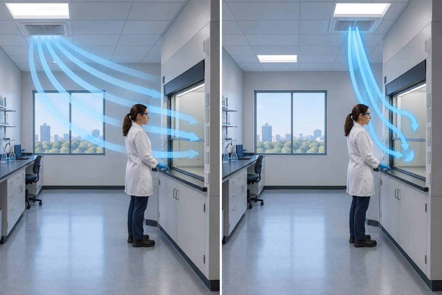
Side-by-side room sections comparing supply air introduced at the opposite end of the lab at low velocity, which sweeps the breathing zone before reaching the hood, with a diffuser placed close to the hood that forms a jet against the face and short-circuits into the exhaust
Makeup Air Temperature, Reheat and Comfort in the Room
When Makeup Air Volume Turns Into a Draft Complaint
Comfort problems in labs scale with supply volume, which means the moment you increase makeup air to cover exhaust, you create a draft question. The same diffuser that was unremarkable at one airflow becomes a complaint at a higher one, and the people who notice are usually the ones working at a bench for a full shift.
Two things make this a design problem rather than a human one. First, the airflow you are supplying is outdoor air, so it arrives at outdoor temperature in both heating and cooling seasons unless it is conditioned. Second, a lab’s occupant load is low relative to its air volume, so the air change requirement, not the people, is usually what sets the flow.
The result is a room that moves a lot of air past a small number of people. Reported symptoms follow the geometry: a diffuser that throws across a bench produces a persistent draft, and a high supply volume through a small diffuser produces a high-velocity airstream even when the total room airflow is correct.
Supply Air Treatment and Reheat: Mechanism and Cost Consequences
Makeup air has to be brought to a supply condition before it enters the room, and the energy to do that is proportional to volume and to the difference between outdoor and room conditions. Raising supply volume therefore raises both the heating and the cooling side of the load, and it can do so at the same time in different seasons.
Reheat enters when a single supply stream has to serve zones or rooms with different requirements. Cooling a shared airstream to satisfy the hottest load and then reheating it for the colder zone is a familiar and expensive pattern, and it becomes more expensive as the airflow rises. No authoritative limit on makeup air supply temperature or reheat strategy was located in the sources for this subject, so the honest statement is mechanism and consequence rather than a target temperature.
The practical consequence is that airflow decisions carry an operating cost beyond the fan. When you raise makeup air volume to satisfy a pressure or exhaust target, you also commit to conditioning that volume year round, and to the reheat that a shared system may need.
A quick way to keep that visible is to record supply volume, supply temperature setpoint source and whether terminal reheat exists for the room, alongside the airflow figures. That record is the difference between a design that shows its operating cost and one that hides it.
Comfort as a Constraint, Not an Add-On
Comfort in a lab is not decorative, because the same airflow that makes a room uncomfortable also makes people work around it. The regulatory framing is instructive here. OSHA’s laboratory chemical hygiene provisions require engineering controls and require that protective equipment, including fume hoods, be maintained in working order. The non-mandatory Appendix A guidance sets out the hierarchy of controls, placing engineering controls before administrative controls, work practices and personal protective equipment, on the grounds that engineering controls isolate people from the hazard physically.
Everything in this step is engineering control, whether it is labeled airflow or comfort. Supply air that reaches a working position as a cold draft is the reason an operator closes a sash to stand behind a barrier, and a closed sash changes the exhaust volume the room was balanced around. The safety case for managing comfort is that it protects the operating condition your balance assumed.
Next, when a hood is selected on airflow, the exhaust fan selection has to be able to hold that flow against the pressure your room and ductwork impose.
Comfort and containment are the same conversation in a laboratory, so decide them together rather than treating ventilation as settled before comfort is raised.
VAV Fume Hoods: Supply and Exhaust Air Coordination
The Three Control Loops: Hood, Duct and Room
A variable volume lab runs three control loops at once, and makeup air is what ties the third one to the other two. The hood loop holds face velocity as the sash moves. The duct loop holds static pressure in the exhaust riser so the hood loop has something stable to work against. The room loop holds the pressure difference by tracking supply against exhaust, which is the loop that makeup air belongs to.
| Loop | What it controls | Sensor | What goes wrong when it fails |
|---|---|---|---|
| Hood | Airflow at the hood, as sash position changes | Sash position sensor and airflow measurement | Face velocity drifts out of range; the hood is the symptom, not the cause |
| Duct | Static pressure in the exhaust system | Pressure sensor in the riser or at the fan | Every hood on the riser reacts at once; the room balance follows |
| Room | Supply-to-exhaust offset, and therefore room pressure | Room differential pressure or airflow tracking | Room goes positive and the directed airflow into the lab is lost |
The room loop is the one that determines whether your makeup air volume is actually delivered as offset. It can be built around a pressure measurement, an airflow tracking comparison of supply and exhaust, or a combination, and the choice changes how the room behaves when a sash moves or a door opens. In a tracking arrangement, supply and exhaust volumes are compared continuously, and the offset is held by modulating the room controller and its dampers.
Which control architecture fits a given lab is a separate selection question, covered where airflow control strategy is compared in full. The point to carry into a makeup air design is that the room loop is a control requirement with a measurable acceptance criterion, not a setting. On the equipment side, that requirement lands on the VAV control dampers and the room-level devices that hold the offset.
How Fast a System Must Respond When the Sash Moves
Response speed is where a design that looks correct on a balance sheet fails in service. When an operator lowers a sash, hood exhaust drops immediately and the room loop has to reduce supply to match, or the room swings positive. Institutional design material states a requirement in exactly these terms: airflow tracking must maintain the pressure difference between adjacent spaces, and the differential must not remain outside its range for more than two minutes, with that interval adjustable.
The same clause adds a direction requirement: the designed airflow direction must not reverse under fault conditions. Read the two together and you have a shaped requirement rather than a single value. A room may be transiently outside its range while the loops rebalance, and the acceptance test is how long that may last. The direction, by contrast, is absolute: an excursion that reverses airflow out of the lab is a failure even if the pressure recovers within the allowed interval.
For a retrofit, the practical consequence is that the existing room loop may be the limiting item, not the new hood. A constant volume system that has no room loop cannot hold an offset as sash positions change, so adding a VAV hood to it creates a coordination requirement the room cannot currently satisfy.
Sash movement is also the test input for commissioning. The measurable acceptance criteria are the recovery interval and the direction held during the excursion, and both are recorded as observed values rather than as settings.
Airflow Tracking and Pressure Control Are Different Requirements
Pressure control and airflow tracking are often used as synonyms, and they are not the same thing. Pressure control holds a differential between a room and its reference space. Airflow tracking holds a relationship between the supply and exhaust volumes of a space. A room can satisfy one and fail the other, and the failure looks different in each case.
Tracking has no single correct value of its own. Its target is the offset that produces the pressure your specification asks for, and that offset changes with the room’s leakage behavior and with door position. A tracking loop with a fixed offset target will hold that offset while the resulting pressure varies with door state, which is exactly the behavior a fixed setpoint produces.
Pressure control, by contrast, reads the differential directly and drives the offset until the reading matches. That architecture reacts to leakage changes, and it reacts to door openings by moving air volumes in ways that can be limited by control design.
The practical difference for a project document is what you write down as the requirement. If you write a pressure target, you are asking for a measured differential with a range. If you write an offset, you are asking for a volume relationship, and the resulting pressure is an outcome you must verify separately.
Full Fresh-Air Supply and Recirculating Rooms
Makeup air can come from an all-outdoor-air supply system or from a system that uses some recirculation, and the choice changes what the supply air is allowed to carry. Where recirculation is used, institutional design material requires that the central air handling unit be able to supply the outdoor air needed to maintain the space’s pressure direction, and to provide makeup air that supports the space’s exhaust demand. Both duties rest on the same unit, which is why a recirculating design is not a way to avoid the makeup air calculation.
The distinction that gets lost is between volume and quality. A 100% outdoor air supply is a statement about what the supply contains. A makeup air volume expressed as a fraction of exhaust is a statement about how much air moves. A recirculating room can meet the volume requirement and still fail the quality intent if the central unit cannot deliver the outdoor air fraction the space needs.
For a retrofit, that becomes a capacity question about the existing air handling unit. If the unit cannot supply the outdoor air the room requires while also serving its other zones, the makeup air solution has to be local to the room.
State the three requirements separately in your documents: the outdoor air fraction, the makeup air volume, and the pressure target. Separating them is how you can name the room control approach and the air valve that will hold your offset, and how you can tell whether your existing air handling unit has the capacity left to serve the room at all.
Commissioning the Balance: Room-Side Verification Points
Why Commissioning Covers More Than Hood Face Velocity
Most commissioning checklists in circulation test the hood, and the hood is only half the system. Face velocity, sash alarms, airflow monitor calibration and tracer gas containment all describe the cabinet. None of them describes whether the room supplied the air that the cabinet exhausted, which is the question makeup air exists to answer.
A room can pass every hood test and still fail in service, because the failure mode is a room-side one. If supply does not track exhaust, the pressure direction drifts and the hood begins drawing air from wherever it can, including door gaps and adjacent spaces. The cabinet still measures acceptably at the face while the room around it has stopped working as designed.
Room-side commissioning is what catches that divergence between a passing hood test and a failing room. It also produces the baseline that later testing is compared against, which is why the record matters as much as the test. A measured value without its conditions cannot be compared with anything later.
Room-Side Verification Points
| Verification point | Limit or relationship | Conditions and source type |
|---|---|---|
| Room pressure differential, direction and magnitude | The direction and magnitude the specification requires | Doors closed, ventilation running normally |
| Pressure recovery after a disturbance | Recovery within the allowed interval, with direction never reversing | Force a sash movement or a door cycle, then observe |
| Supply diffuser jet velocity | Below the stated threshold relative to hood capture velocity | At the face of each supply outlet influencing the hood |
| Room air speed in the hood face area | Not to exceed 20–25 fpm, which is an upper bound to stay under rather than a target to hit | Measured with hood exhaust off, per the federal technical standard |
| Air balance across the room | The offset the room holds matches the design offset | Supply and exhaust volumes measured together |
| Door operation at the design differential | The differential stays within the range people can operate doors against | Doors closed and held, then opened normally |
The fourth row is the one most often omitted, because the test condition is counterintuitive: the requirement states that it is measured with hood exhaust off, which separates the supply system’s contribution from the hood’s own inflow. Running that measurement with the hood operating measures a different quantity and cannot be compared with the limit. Read the value as a ceiling to stay below: a reading well under 20 fpm is a pass, not a shortfall.
The second row is the one most often reduced to a spot reading. A single static measurement of room pressure confirms that a room is quiet, not that it recovers. The requirement is about behavior over time, so the test has to create an excursion and watch what happens next.
Periodic Retesting and Who Owns the Documented Result
Commissioning produces a baseline, and a baseline is only useful if something is compared against it. Airflow drifts as filters load, dampers settle, belts wear and rooms get reconfigured. A pressure reading taken at handover describes the room on one day.
Retesting intervals are set by project specification, institutional policy or the requirements of the authority having jurisdiction rather than by a universal number, so the interval belongs in the project documents. What can be stated generally is what to record: the measurement, the conditions it was taken under, the instrument, and the date.
Ownership is the part that gets dropped in retrofits. The entity that signs the acceptance test should be named in the specification, and the party responsible for periodic retesting should be named as well, because they are often not the same organization. A maintenance contractor, a facilities group or an internal EHS function can each hold that role, and the record needs to say which one does.
Requirements for inspection, testing and maintenance of laboratory ventilation sit alongside fume hood inspection practice, and the two belong in the same schedule even though they measure different things.
What This Verification Does Not Cover: ASHRAE 110 and ANSI/ASSP Z9.5
Two standards are frequently cited in this territory, and the scope of each is stated here rather than its provisions, because their full texts were not obtained. ASHRAE 110 addresses the performance of a fume hood as a containment device, tested at the cabinet. ANSI/ASSP Z9.5 addresses laboratory ventilation as a system.
The distinction decides which document governs a given test. A tracer gas containment test is a hood performance test, and the room-side points above do not replace it. Conversely, a hood performance test says nothing about whether the room’s supply tracks its exhaust.
A commissioning scope that names both families of tests covers the system without asking either document to prove something it was not written to address. The room-side points above serve as the balance test, and the cabinet performance tests sit under their own standard.
Write the six room-side points into the acceptance scope with their measurement conditions, and name the party that signs the result. With that scope agreed before installation, you can determine at handover whether the room, and not just the hood, was commissioned.
Retrofit Reality: Adding a Hood to an Existing Lab
Retrofit Constraints That Show Up After the Order
Adding one hood to a working lab looks like a small project until the building starts answering back. Five constraints decide whether it stays small, and four of them have nothing to do with the hood.
| Constraint | The question it raises | Who can answer it |
|---|---|---|
| Existing exhaust capacity | Is there spare airflow in the riser and at the fan? | Mechanical engineer of record, from the fan schedule and test data |
| Vertical and roof path | Can a new duct reach the roof without crossing occupied space or occupied roof? | Design team with the building drawings |
| Ceiling depth and transport route | Does the hood and its ductwork physically fit to the room? | Contractor, from a site survey |
| Mechanical permit and acceptance authority | Which inspections must this installation pass, and who signs them? | Local authority having jurisdiction |
| Makeup air unit and its treatment cost | If the central unit has no capacity, what supplies the room instead? | Mechanical engineer of record plus the facilities budget owner |
Capacity is the constraint that most often converts a simple order into a system project. A hood that adds exhaust volume also adds supply volume, and the supply side may need a new unit, a new heater or new ductwork of its own.
The permit and acceptance question deserves early attention because it can constrain the technical solution. Where the authority having jurisdiction requires documented pressure readings at handover, the room loop has to be capable of producing them, which is a different requirement from simply having a hood that works.
Reading Existing Capacity: What the Records Usually Miss
Records for an existing lab are frequently a set of drawings with a commissioning report that no longer describes the room. Three gaps matter for a hood addition.
The first is the actual operating airflow of existing hoods. A fan is selected at a design point, and a running system delivers what its installed conditions allow. A measured airflow at the existing hoods is worth more than a design figure for judging spare capacity.
The second is the room’s leakage behavior. This is not normally recorded at all, and it is what determines how much offset a target pressure will require. A pressure test on the room, or a measurement of the offset at known pressure, provides the working number.
The third is the supply side’s remaining capacity. Even where exhaust capacity exists, the supply system may be at its limit, and a VAV hood that reduces exhaust when sashes close will drive supply down with it, so the question is about turndown as much as about peak flow.
The practical position for a retrofit is to treat measured values as inputs and design values as context. Where measurement is not possible before the order, the gap should be stated as an assumption in the documents rather than left implicit.
Worked Example: One 6 ft Bench Hood Added to an Existing Lab
The scenario: a chemistry lab with one existing 4 ft bench hood is adding a second hood, a 6 ft bench model. The room has a working exhaust riser with unmeasured spare capacity, one supply outlet on the wall opposite the hoods, and doors that open normally at the present differential.
Every number below is either labeled as an assumption, taken from a cited relationship, or listed as a site measurement that must be performed. None of them is a standard value.
| Step | Input | Result, with form and unit | Where the number comes from |
|---|---|---|---|
| 1 | Face velocity at the working sash (fpm); working sash opening on a 6 ft wide hood (ft²) | Exhaust volume for the new hood, in cfm = face velocity x open area | Face velocity is a project design input taken from the face velocity requirement for the application; the open area follows from the working sash height and width, with the working height stated as an assumption. This is a calculation, not a cited value. |
| 2 | Hood count and simultaneous use assumption (fraction) | Room exhaust total, in cfm | Two hoods; assumption stated as both operating during normal work, with the existing hood at its measured operating airflow if available, otherwise at its design airflow |
| 3 | Target room differential (in. w.c. or Pa) and the room’s leakage behavior | Permitted supply-to-exhaust offset, in cfm | Offset is not a cited figure. It must be derived from the pressure target and a measured room leakage or offset-at-pressure value, or stated as a design assumption for later confirmation. |
| 4 | Room exhaust total (cfm) minus permitted offset (cfm) | Makeup air volume required for the exhaust balance, in cfm | Arithmetic on steps 2 and 3 |
| 5 | Room cooling load converted to supply volume (cfm) | Governing makeup air volume, in cfm, as the larger of the two figures | The larger of cooling-driven supply and exhaust-driven supply governs; where exhaust exceeds the cooling-driven figure, supply must be increased to cover the difference |
| 6 | Diffuser selection (model, face size) and its throw pattern | A pass or fail against two velocities: diffuser jet (fpm) versus hood capture velocity, and room air speed at the hood face (fpm) against the stated upper bound | Check the supply outlet position relative to both hoods, the jet velocity relative to hood capture velocity, and the room air speed in the hood face area with hood exhaust off |
| 7 | Steps 1 to 6 combined | A stated project position in three units (cfm, cfm, in. w.c.) plus a list of measurements | Conclusion below |
Step 1 deserves a note on why it is written as an input rather than a number here. The exhaust volume follows from the face velocity the project specifies and the sash opening the operators actually use, and both of those are project decisions covered in their own right. Stating a single airflow figure for a hood without its sash condition is the error step 6 is written to catch.
Step 3 is the one that most often gets filled with a percentage from memory. It should not be. The offset is an output of the pressure target and the room’s leakage behavior, and the honest version of step 3 in a preliminary document is a range plus the measurement that will confirm it.
Step 6 is where a correct volume can still fail. The new supply requirement is larger than the old one, and the single existing wall outlet has to deliver more air into the same room. The room air speed in the hood face area is the check, measured with hood exhaust off, and the diffuser jet relationship to capture velocity is the design constraint behind it.
Final Verdict for This Project, and the Step That Needs Site Data
Assuming the measured exhaust capacity supports the additional volume, the project position is this. Increase room makeup air to the governing volume from step 5, rebalance the room so the offset from step 3 is held, and verify the supply path against both hoods before accepting the installation.
If the existing exhaust capacity cannot support the added hood, that comes first. Makeup air cannot be designed around an exhaust system that cannot carry the flow, and the sequence inverts: exhaust capacity, then makeup air volume, then pressure offset, then the supply path.
Four items require site data or professional review, and they should be named in the project documents rather than assumed. The first two belong to the exhaust side: the measured operating airflow of the existing hood and the spare riser capacity, then the room’s leakage behavior expressed as a measured offset at a known pressure. The last two belong to the supply and door side: the actual condition of the supply system including its turndown, and the door operating force at the design differential.
The conclusion you can carry to a contractor is a set of three requirements stated in units: this makeup air volume in cfm, held as this offset in cfm, producing this pressure differential in in. w.c., with these measurements named as the ones that confirm it. That is a specification someone can price, and it is also the specification that a commissioning scope can be written against.
With that package in hand you can now decide whether to proceed to procurement or to commission a capacity survey first. Before you order, confirm the four site items above; they are the difference between a specification that gets built as drawn and one that gets renegotiated on site.
Standards That Touch Fume Hood Makeup Air Requirements
Standards Table: Which Document Addresses Which Part
Standards and regulations in this territory divide by scope, and the division explains why a search for the governing document returns several answers. The table states what each document covers, and how each one is used below, along with whether its full text was obtained.
| Document | Scope it addresses | How it is used below | Full text obtained |
|---|---|---|---|
| OSHA 29 CFR 1910.1450 | Laboratory chemical hygiene; requirement to maintain engineering controls and protective equipment, fume hoods included, in working order | Cited as a regulatory requirement in its own terms. Its Appendix A guidance on the hierarchy of controls is non-mandatory and is identified as such wherever it is used. | Yes, regulation text |
| NIH ORS Design Requirements Manual | Institutional design requirements for laboratory facilities: directed airflow, pressure limits, airflow tracking behavior, makeup air governing rule | Cited for design requirements and for the rule that makeup air must satisfy cooling load and exhaust demand, whichever is larger. Institutional manual, not a regulation. | Yes |
| University design guidelines (two independent institutions) | Design values for makeup air volume and airflow path at the room level | Cited for the institutional design value of makeup air at 90% of exhaust, and for path rules. Institutional positions, not code. | Yes, both |
| CDC infection control guidance | Pressure differential magnitude for healthcare spaces | Cited with its healthcare scope attached, as a magnitude reference. | Yes |
| EPA 1978 laboratory fume hood standards | Makeup air behavior at the hood face, including speed limit and measurement condition | Cited for the air speed limit in the hood face area and the condition under which it is measured. | Yes |
| UKY fume hood building design criteria | Supply diffuser jet velocity relative to hood capture velocity | Cited for the proportional relationship. | Yes |
| ASHRAE 62.1 | Ventilation for acceptable indoor air quality | Stated by number and scope only. | No |
| NFPA 45 | Fire protection for laboratories using chemicals | Stated by number and scope only. | No |
| ANSI/ASSP Z9.5 | Laboratory ventilation system design and operation | Stated by number and scope only. | No |
| ASHRAE 110 | Performance testing of fume hoods as containment devices | Stated by number and scope only. | No |
The last four rows are stated in the same table for a reason. Their numbers appear constantly in secondary sources, and their provisions are not restated here, because their texts were not obtained. Where a secondary source attributes a figure to one of them, that attribution is a secondary source’s statement.
Why a Standard Number Does Not Make a Number a Legal Requirement
Five kinds of document get treated as interchangeable, and they are not. A regulation is enforceable law. A standard is a consensus document that becomes enforceable through adoption by a jurisdiction or through a contract. An institutional design manual is binding inside the institution that publishes it. A design guideline is a recommendation, or a requirement if a project specification adopts it. A project specification is what your installer is actually held to.
The distinction has a concrete consequence for a number like the makeup air design value of 90% of exhaust. Two independent university guidelines use it, which makes it a widely used institutional design value and a reasonable starting position. It does not make it a legal requirement, and it does not bind a project that specifies something else.
The reverse error is also common. Where a project specification adopts a design guideline and no regulation sets a value, the guideline is the enforceable requirement even though it is not law. Enforcement comes from the document chain, not from the authority of the publisher.
The practical test is to ask which document in your project’s chain states the requirement and which party can hold you to it.
Where the Numbers Stop: Boundaries Stated in Plain Terms
Four boundaries apply to the material below, and they are stated rather than left implicit.
No universal legal value exists for makeup air volume as a percentage of exhaust. Institutional design values exist, and the governing calculation exists, and those are what follow from here.
No authoritative single value exists for a minimum air change rate in a chemistry laboratory. Figures that circulate for air changes per hour come from animal facilities and clean or classified spaces in the institutional material reviewed, and they do not transfer to a chemistry lab.
No government source obtained for this subject sets an absolute air speed limit for cross drafts at a hood face. The portable form is a proportion of the hood’s average face velocity, which travels between hoods of different sizes and does not depend on an absolute number.
No authoritative limit was obtained for makeup air supply temperature or reheat strategy. The mechanism and its operating cost consequences are described; a target temperature is not.
Specialty applications have their own requirement sets, and hoods serving them are covered separately. Perchloric acid service and explosion-proof installations each carry their own requirements, and neither is settled by the room-level material above.
The scope of a claim is part of the claim. When you write a makeup air requirement into a project document, name the document you are taking it from: a regulation, a standard, an institutional manual, a guideline, or your own specification. That is how you can determine which requirement your contractor is bound by.
Frequently Asked Questions on Makeup Air and Pressure Balance
Do Fume Hood Makeup Air Requirements Apply to Kitchen Range Hoods?
No. Kitchen range hood makeup air provisions address cooking effluent and fuel-burning appliances rather than laboratory hazards. In dwellings, that is the IRC M1503.4 territory cited in residential search results; commercial kitchens fall under commercial kitchen exhaust provisions, which are a separate set again.
A laboratory fume hood is a different device serving a different hazard, and the room it sits in is balanced differently. Residential practice often uses a smaller supply inlet or a pressure relief strategy, because the goal there is avoiding backdrafting of combustion appliances.
In a lab, the direction of the room pressure is what protects the corridor, and makeup air is part of an engineered containment strategy rather than a comfort detail.
At What CFM Is Makeup Air Required for a Laboratory Hood?
There is no threshold value that triggers makeup air. Any hood that exhausts air from a room requires the room to be supplied with an equivalent volume, reduced by whatever offset holds the pressure target.
The quantity is therefore an outcome of two calculations. The first is the room’s exhaust total from its hoods. The second is the offset that the pressure target and the room’s leakage behavior permit.
You can set the makeup air volume for a project by subtracting the permitted offset from the exhaust total and checking the result against the room’s cooling load.
Can a Fume Hood Share Makeup Air With the Rest of the Building?
Yes, provided the shared supply can carry both duties for that space. The central air handling unit has to supply the outdoor air the space needs and the makeup air volume its exhaust demand requires, and both duties fall on the same unit.
That makes a shared supply arrangement a capacity question rather than a design shortcut. Where the unit cannot serve the room’s demand alongside its other zones, the makeup air has to be provided locally, and the pressure direction in adjacent spaces has to survive the arrangement.
What Happens If Makeup Air Is Undersized?
The room’s negative pressure deepens, and the first symptom is usually at the door. A differential large enough to make doors difficult to operate, or to produce whistling at gaps, is what an undersized supply system looks like in practice.
The second effect is on the airflow pattern at the hood. When supply cannot cover the offset, exhaust pulls air through whatever leakage paths exist, including door gaps and wall penetrations, and those paths introduce directional air movement across the room.
The cabinet may still read well at the face while the room around it has lost its balance, which is why room-side pressure and airflow are measured separately from hood performance.
Is a Makeup Air Unit Always Required?
Not always as a separate unit. A room’s makeup air can come from a central air handling unit’s outdoor air supply, from a dedicated makeup air unit serving the room or the floor, or from transfer air drawn from adjacent spaces, subject to the pressure direction those spaces must maintain.
The deciding question is not which arrangement is preferred but whether the chosen one can deliver the volume that satisfies both the cooling load and the exhaust demand, taking the larger. Where the central unit cannot, a dedicated unit is what remains.
Directional requirements also constrain transfer air, because air pulled from an adjacent space changes that space’s balance.
Who Is Responsible for Verifying Room Pressure After Installation?
A qualified testing, adjusting and balancing provider performs the measurement under the project specification, and the authority having jurisdiction or the project’s designated acceptance party establishes what is required and who signs it.
The responsible party for periodic retesting is a separate appointment and should be named explicitly, because the installing contractor is rarely the entity that retests years later.
The verification itself has two parts: the held pressure, and the system’s behavior when a sash or a door disturbs it, including the recovery interval and the direction.
Fume Hood Exhaust and Supply Air: What to Decide Before You Order
Three Statements to Put in Your Project Documents
A makeup air specification that can be priced and commissioned has three lines, and each one is stated in units rather than as a range of intent.
| Statement | Form to write | Why it is written this way |
|---|---|---|
| Makeup air volume | A flow rate in cfm, derived from room exhaust minus the permitted offset, and reconciled against the room cooling load, whichever is larger | A volume is what a supplier can size equipment against and what a balancer can measure |
| Room pressure target | A direction, a magnitude and an upper bound, for example negative to the corridor, near 0.01 in. w.c., and below the differential at which doors stop operating normally | One number without a range invites a reading that no room can hold |
| Airflow offset | A permitted difference in cfm between supply and exhaust, tied to the pressure target and to the room’s measured leakage behavior | Stating an offset lets the room loop be selected and set, and it prevents a percentage from being substituted |
Three supporting statements belong beside them. The supply path requirement, expressed as supply opposite the hoods and outside the path between door and hood face. The hood-face air speed limit, including the measurement condition that it is taken with hood exhaust off. And the acceptance scope, listing the room-side measurements and naming the party that signs them.
Equipment selection follows from those lines rather than leading them. Where the offset has to be held while sash positions change, the room loop and the airflow control devices that serve it are the items under selection, and the choice of airflow control approach and valve type is a specification decision rather than an interchangeable part. Use the airflow figures here to choose VAV control dampers, pair them with a venturi air valve where the exhaust side has to stay pressure independent, and select hoods and cabinets for the room against the same numbers.
The Next Step
Work the sequence in order and stop where a measurement is missing. Write the exhaust total from your hoods, derive the permitted offset from a pressure target and the room’s leakage behavior, subtract to get makeup air volume, and check it against the cooling load.
If any input is unknown, name it as a measurement to be taken rather than filling it with a familiar figure. The inputs most often missing on a retrofit are the actual operating airflow of the existing hoods, spare capacity in the riser, and the room’s leakage behavior at a known pressure.
Then issue the three statements above as project requirements, with the acceptance scope attached. That package is what a contractor prices, what an installer balances to, and what a commissioning agent can verify, and it is the form of fume hood makeup air requirements that survives contact with a real building.
For volume, path and pressure, the decisions are yours to state and the measurements are the building’s to confirm. Before you order, you can write all three into the specification and name the tests that will prove them.
Leave a Reply