




Key Takeaways
- Fume hood placement requirements are a hybrid of code obligations and institutional design standards. A regulation obliges your employer to keep the hood working properly, while the distances that show up on drawings come from NFPA 45 section 7.9, ANSI/ASSP Z9.5 and the design standard each institution adopts.
- Separate the design value from the acceptance criterion before comparing anything. A distance in feet and a cross-draft limit expressed as a share of face velocity are two different kinds of number, tested at two different times.
- Direction beats speed: air aimed perpendicular at the sash plane does more damage than faster parallel air. Ask which way the supply air travels across the hood face, then ask how fast it travels.
- Door distances in the published guidance span roughly 3 feet to 10 feet, and the 10-foot figure comes from a single upstream clause transcribed in three places. The number is not wrong; the repetition records one institution’s reading of that clause rather than three separate findings.
- A passed containment test does not clear the location. A hood can pass tracer gas containment testing and still carry an excessive cross draft that has to be disclosed in the test report.
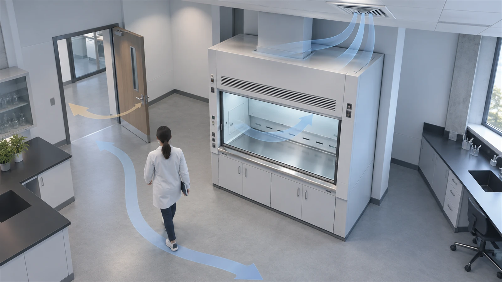
A cabinet’s containment depends on more than the cabinet. The room decides how much air crosses the hood face, and the layout decides whether that air arrives in a useful direction. Placement gets fixed on the drawing, so moving a hood after installation is a change order rather than an adjustment, and a change order at that stage is the expensive way to solve a layout problem. That is why fume hood placement requirements belong in the design conversation and not in the commissioning punch list.
Fume Hood Placement Requirements: Direct Answer and Scope
What Counts as a Placement Requirement Here
A placement requirement is a condition on where a hood stands and what surrounds it, not a condition on the hood itself. It covers the clearance in front of the sash, the distance and direction of supply air terminals, proximity to doors and traffic lanes, and separation from adjacent hoods or equipment. Face velocity, sash height and duct sizing sit outside this page because those are properties of the hood and its exhaust system rather than of the room position.
That boundary matters when you write a spec. A supplier who reads only a face velocity target can deliver a compliant cabinet into a non-compliant location, and every measurement taken afterwards will still show the cabinet working. Position is the part of the overall containment performance that the cabinet cannot supply by itself.
The Short Answer: There Is No Single Number
No single distance, in any unit, satisfies fume hood placement requirements everywhere. Four published sources place a supply air diffuser at 4 feet 6 inches, 5 feet, 5 feet, or 10 feet from the hood, and they are measuring to different reference planes with different diffuser types in mind. A reader who memorizes one value will misapply it.
The practical answer is a range plus a basis. Distances for diffusers, doors and neighboring hoods each run across a published spread; each value in that spread comes from a specific institution’s design standard and names the surface it is measured to. The working judgment is therefore to identify which document governs your project, then read its number against the surface it specifies. The sections that follow give those spreads and the bases behind them.
What This Page Deliberately Leaves to Other Pages
This page answers one question: where should the hood stand, and who decides. The face velocity threshold system belongs to a separate article, because acceptance values for face velocity carry their own test conditions and control implications. Sash height, duct sizing and exhaust fan selection belong to their own pages as well.
Making supply air and pressure balance a single line here is deliberate, and the line still carries a boundary judgment. That judgment is the direction of the supply air terminal relative to the hood, because direction is a property of where the hood stands. The volumes of makeup air and the pressure balance across the room are a separate design problem with its own trade-offs, so they are covered on their own page. You can decide the placement question here and route the balance question to the page that owns it.
The split does not leave a gap in the review. A reader who works only through this page still ends up with a diffuser direction, a distance and a type for every supply terminal that serves a hood, and those three items are what a placement argument turns on. What stays outside is the arithmetic of making supply and exhaust match across the whole room, and that arithmetic is answered elsewhere.
Supply air terminals are the clearest culprit in placement complaints, so start there. Once you can state a diffuser’s distance, direction and type, you can decide whether a proposed hood position is defensible before you sign the drawing.
Which Standards, Policies or Authorities Apply to a Fume Hood Location
Four Layers of Authority: Regulation, Standard, Institutional Policy, Project Specification
Fume hood location requirements sit under four different layers of authority, and each layer answers a different question. A regulation imposes a legal duty on the employer. A consensus standard describes how that duty is normally met. An institutional design standard converts the consensus position into values an architect can draw. A project specification states what this building will be held to.
| Layer | Who issues it | What it fixes | Example in this article |
|---|---|---|---|
| Regulation | Federal or state labour authority | The duty and the outcome | 29 CFR 1910.1450 requires that hoods function properly and that specific measures ensure adequate performance |
| Consensus standard | Standards bodies such as NFPA, ANSI/ASSP and SEFA | Practices and acceptance criteria | The cross-draft limit of 30 percent of face velocity and its field check |
| Institutional design standard | Universities and public agencies | Drawable values with reference planes | A diffuser kept 5 feet from the plane of the sash |
| Project specification | The design team, in the contract documents | The governing edition and the applicable clauses | “Placement per NFPA 45 section 7.9” as written by the responsible design professional |
Two consequences follow from this structure. First, a distance written in a university design standard is not a legal maximum, so treating 5 feet or 10 feet as a code limit misstates what the document proves. Second, when two layers disagree, the argument is settled by the project specification rather than by the strongest-sounding number. A placed hood then moves into installation requirements such as services, supports and clearances, which are a separate family of conditions from the position itself.
What OSHA Actually Requires of a Fume Hood
The United States laboratory chemical hygiene rule requires a written program that keeps fume hoods and other protective equipment functioning properly, and it requires specific measures to ensure their proper and adequate performance (29 CFR 1910.1450). It also requires criteria for selecting engineering controls. No clause in that rule states a distance from a door, a diffuser or a neighboring hood. The rule is written as a performance obligation rather than as a set of figures: it requires the hood to perform, and it carries no velocity figure.
The federal laboratory facilities guidance points the same way: evaluate cross-draft velocities, diffuser type and diffuser location together when judging whether a hood configuration will contain contaminants (EPA facilities manual, Volume 2), and treat location as a planning-stage decision rather than a commissioning fix. The distance itself is left to the standards and to the institution that owns the building.
Why “Many Universities Require 10 Feet” Comes From One Upstream Clause
The recommendation to keep hoods more than 10 feet from any door appears verbatim in design documents from more than one institution, which makes it look like a settled industry figure. The wording repeats because the texts were copied: the passages carry the same reference block — NFPA 45 chapter 6-9.2 and 3-4.1(d), NFPA 99 chapter 5-4.3.2, ANSI/AIHA Z9.5 section 5.4.
Read the three transcriptions as one upstream clause and the picture changes. Other institutions publish 60 inches to a door beside the hood face and 40 inches to a door beside the side panel, or 4 feet 6 inches on the sash side and 3 feet on the side, or 4 feet from an adjacent doorway. One repeated recommendation is not a consensus, and you can decide which figure applies only after you know which document governs the room.
Inventory those four authority layers before you negotiate a distance, because the layer tells you who has standing to settle it. With that in hand, the next question is which kind of number each rule gives you.
Design Target vs Operating Reading vs Acceptance Test
The Three Quantity Types, Defined
Placement numbers fall into three quantities that are produced at three different moments. A design target is a value drawn on the documents before anything is built. An operating reading is what an instrument shows on a running hood. An acceptance criterion is the limit a test must meet for the installation to be signed off.
| Quantity type | Typical form | Produced when | Placement examples |
|---|---|---|---|
| Design target | A length with a reference plane | On the drawing | Diffuser at least 5 feet from the hood face; minimum 5 feet from the plane of the sash unless CFD or a mockup justifies less; diffuser not within 4 feet 6 inches of the sash |
| Operating reading | A measured velocity at the face | During operation, per survey | Face velocity read at the working opening; cross-draft velocity measured in front of the hood |
| Acceptance criterion | A ratio, or a velocity with a stated direction | During the field test | Cross drafts not above 30 percent of the operating velocity; cross drafts not above 30 percent of face velocity |
Confusing the columns is the most common error in a placement argument. A designer who answers a commissioning complaint with a five-foot drawing dimension answers a question about operation with a document about intent, and the complaint stands. A tester who writes a design target into a measurement record has recorded an opinion rather than a reading.
Which Surface the Number Is Measured To
Every diffuser distance in the published guidance needs its reference plane named before it means anything. One federal facilities manual puts diffusers at least 5 feet from the face of any fume hood. An institutional standard requires 5 feet between the diffuser and the plane of the sash, unless a CFD study or physical mockup justifies less. A second institutional standard keeps any room supply diffuser 4 feet 6 inches clear of the sash.
Those three values look almost identical and are not interchangeable. The face of the hood and the plane of the sash are different surfaces on the same cabinet, and a drawing dimension measured from one governs a different physical clearance than a dimension measured from the other. A fourth source sits much further out, at 10 feet, and applies only to directional supply diffusers. One standard also caps diffuser performance rather than distance: throw velocity at 60 feet per minute or less, and supply air at the sash opening no faster than 50 feet per minute.
The same discipline applies to cross-draft limits. A limit expressed as a share of face velocity scales with the hood setting; a limit expressed in feet per minute does not, so a 30 feet per minute ceiling at the hood face and a 30 percent ratio are different instruments for different purposes. Compare values only after you have matched quantity type and reference surface, and you can state which of two numbers is the binding one for a specific clause.
Why Direction Matters More Than Speed
Air that arrives perpendicular to the sash plane does more harm than faster air that arrives parallel to it. An institutional design standard states this directly: air directed perpendicular to the plane of the sash can be more detrimental to hood performance than cross drafts of similar velocity directed parallel to the opening.
Measurement practice follows from that ranking. Performance testing procedures that check for cross drafts require the probe orientation to be included, because the perpendicular component is normal to the sash plane and does not show up in a parallel-only survey. A velocity number without its direction is an incomplete reading.
This is why a placement review asks for the diffuser’s throw direction and the air pattern across the face before it asks for a velocity limit. Thirteen published sources on hood placement were examined for this article, and twelve of them discuss distance or general airflow without stating the direction rule at all, which leaves the strongest available judgment largely unused in practice.
Where the Cross-Draft Velocity Criteria Disagree
Cross-draft limits do not agree across published sources, and the disagreement is structural rather than a typographical slip. SEFA 1 requires field verification with a thermal anemometer and a smoke source that cross-draft velocity stays at or below 30 percent of the operating velocity, and any draft above that value is to be eliminated before the hood test continues. A university standard sets the same ceiling at 30 percent of face velocity and adds an ideal target of 20 percent.
A third institution uses a two-condition rule instead: cross drafts are not to exceed 50 feet per minute or 50 percent of hood face velocity, whichever is less, with diffuser throw limited to 60 feet per minute. A federal facilities manual writes the limit as an absolute velocity, namely 30 feet per minute in any direction at the hood face.
Four sources, three different structures. A ratio-only limit, a ratio with an ideal target, a two-condition take-the-lesser rule, and an absolute velocity ceiling cannot be averaged into one figure, and picking the most convenient one would misrepresent the others. Decide per project: name the document that governs the room, apply its structure, and record which one you applied. The face velocity thresholds these ratios are calculated against are set out in face velocity requirements, which is the reference the ratios depend on.
Separate the three quantity types on any placement document you receive, and you can decide which numbers are binding values and which are only field observations. Supply air terminals then become the first condition to test in detail.
Supply Air Diffusers: Placement Requirements and Separation Distances
Distance from the Hood Face: Four Published Values and Their Bases
Supply air diffusers produce the most placement failures that get blamed on the hood. The distances published for fume hood cross drafts caused by supply terminals do not agree, and the values need to be read as a spread with a basis rather than as competing candidates for one correct figure.
| Source | Distance | Measured to | Applies to | Additional condition |
|---|---|---|---|---|
| Federal facilities manual | At least 5 ft | Face of any fume hood | Diffusers generally | Locate to the side of the hood rather than in front; do not short-circuit airflow into the hood |
| Institutional design standard | 5 ft minimum | Plane of the sash | Diffusers generally | Unless a CFD study or physical mockup justifies less |
| Institutional EHS standard | Not within 4 ft 6 in | Sash | Any room air supply diffuser | Must not affect hood performance |
| Institutional EHS standard | Not within 10 ft | Hood | Directional supply diffusers only | Must also not discharge air toward the hood |
The 10-foot value is the outlier and the reason is written into the clause: it governs directional diffusers, which discharge with a defined throw, while the shorter values govern room diffusers in general. A specification that copies the largest number onto every diffuser over-specifies the room, and a specification that copies the smallest onto a directional diffuser under-protects the hood.
Two more room conditions belong in the same review. Institutional design standards tie higher air change rates to placement risk, requiring special supply air distribution where a laboratory runs above 15 air changes per hour so that containment is not affected by cross drafts. A second standard requires that cabinets and other structures not block or reduce the effectiveness of supply or exhaust air.
Direction, Throw and Diffuser Type
Diffuser selection is a placement decision because it fixes the air pattern that reaches the hood face. One institutional standard permits low-throw, low-velocity perforated diffusers and states that louver and air nozzle grilles are not acceptable, so the type is limited before the distance is argued. Another requires supply registers to be laminar rather than bidirectional in order to avoid producing cross drafting.
Throw is capped separately from distance in at least one standard, at 60 feet per minute for diffuser throw and 50 feet per minute at the sash opening, while a federal manual writes the same concern as a velocity ceiling at the hood face of 30 feet per minute in any direction. Those are two different structures for the same physical risk, and neither converts into the other.
Placement also has to respect the exhaust side of the room. Supply air distribution systems are required to minimize turbulence, with exhaust grilles and registers located away from supply diffusers so that airflow crosses the room at a uniform low velocity. A diffuser placed to satisfy a distance rule while the exhaust register sits beside it can still deliver a turbulent pattern at the hood face.
Diffuser Placements That Are Always Wrong
Some diffuser positions are written as prohibitions rather than distances, and those clauses decide the layout before any measurement is taken. Diffusers are never to be directed toward the hood or at an oblique angle to it, and a diffuser located directly above the hood can create turbulence that carries contaminants out into the room.
Being below or adjacent to supply or exhaust vents is prohibited by a third standard, which groups vents with doorways, high traffic areas and windows as conditions that compromise hood effectiveness. That clause is expressed as a design obligation rather than a clearance, so a drawing cannot discharge it by writing a dimension next to a diffuser.
Read the prohibitions as a first-pass filter on the layout. Move the terminal, or move the hood, while the drawing is still open; after installation, the remediation is a change to the room rather than to the cabinet, and the cost sits with whoever owns the ceiling.
Operable Windows and Room Pressure as Placement Inputs
Two room features change how much air crosses the hood face, and both are settled at placement rather than at commissioning. Operable windows are treated in opposite ways by two institutional standards: one removes the hood from their reach by keeping it away from operable windows, and the other removes the source by specifying that operable windows are not to be provided in the first place.
Room pressure is the second input, and it belongs in a placement review because the hood face is where a pressure imbalance shows up first. A laboratory is to be designed to hold negative pressure relative to adjacent non-laboratory areas, because harmful aerosols can escape the room containment when the room is not negative to those areas. Air moving through an open door beside the hood, an open window or supply grille to one side, and high-velocity air from ceiling diffusers are the three sources a field survey is instructed to check.
Placement owns the direction and position of the supply terminal; the volume balance between supply and exhaust across the room is a wider task. That balance, its calculation and its control scheme are covered in makeup air and room pressure balance, and a placement review should hand the balance question over rather than settle it.
Judge a diffuser on distance, direction and type together, and you can decide whether a proposed hood bay survives its own ceiling layout. Doors and foot traffic are the next condition with the same ability to break a hood that measures well on paper.

Doors, Aisles and Traffic: What Changes When People Move
How Far Should a Fume Hood Be From a Door
The question of fume hood distance from door has the thinnest published evidence base of any placement condition in this review. Of thirteen sources examined, only one gives a door distance as a number; nine describe the risk in words, and three do not mention doors at all.
| Source | Distance | Measured to | Structure |
|---|---|---|---|
| Transcribed recommendation (institutional design documents) | More than 10 ft | Door or doorway | Single value, stated as a recommendation |
| Institutional design standard | 60 in clear to the door adjacent to the face, 40 in clear to doors adjacent to the side panel | Face side and side panel | Two-tier, applies only when a hood cannot avoid sitting between adjacent doors |
| Institutional EHS standard | At least 4 ft 6 in on the sash side, at least 3 ft on the side | Sash and hood side | Two-tier, applies to any doorway |
| Institutional design standard | At least 4 ft | Adjacent doorways and main traffic aisles | Combined with aisle rule |
The spread runs from 3 feet to 10 feet for the same physical relationship. None of those sources is careless; they answer different questions. The two-tier clauses separate a doorway that faces the hood opening from one that faces a side panel, on the reasoning that the opening is the surface that loses containment first. A single-value rule collapses both cases into one number and then has to be applied twice, once to each side, where it will over-constrain one and under-constrain the other.
Read the clause structure before you read the figure. A rule that distinguishes face side from side panel tells you which direction the room should grow; a rule with one value tells you only that someone once chose a number that felt safe for the worst case.
Why the Published Door Distances Disagree by 3 Feet to 10 Feet
The 10-foot figure is not a consensus that other institutions watered down. Three separate design documents carry the recommendation verbatim, and two of them reproduce the citation block in the same order, which identifies them as transcriptions of one upstream clause rather than three independent measurements.
That upstream clause points into the standards that govern laboratory ventilation, and the federal guidance that owns hood layout in the United States is often named as NFPA 45 section 7.9. Those standards are copyrighted documents that this page does not reproduce, and no authorized copy was available while it was written, so this page does not state their internal requirements and does not claim to cover them. Where your specification invokes one of them, consult the edition your project adopts. What can be verified here is the transcription chain, and it changes how the number should be weighted.
Counting transcripts as evidence is the specific trap here. Three documents agreeing looks like a stronger signal than one document stating a figure, but agreement produced by copying carries the weight of a single source. The shorter values come from institutions that wrote their own design requirements against their own laboratory stock, which makes them independent of each other even though they are less frequently quoted.
The same discount applies in reverse. A figure appearing once is not automatically weak if the institution behind it maintains laboratories and publishes its own standard; a figure appearing three times is not strong if the three appearances share one ancestor. Weight the provenance, not the count.
Aisle, Egress Path and Traffic Lane Conditions
Foot traffic is a placement condition because a person walking past a hood disturbs the air at its face. One institutional EHS assessment states that a person walking past the hood can create enough turbulence to disrupt a face velocity of 100 feet per minute, which is a useful order of magnitude for anyone who assumes a passing technician is harmless.
Hoods are to be positioned away from high-traffic lanes inside the laboratory, and away from the activities or facilities that generate air currents or turbulence in the first place. Two further constraints come from egress planning rather than from airflow: hoods should not sit adjacent to a single means of access to an exit, and they should be located away from laboratory exits so that occupants do not have to pass in front of a hood while evacuating. The recurring checks that catch a shift in those conditions over the life of the hood are set out in the inspection checklist.
The mitigation menu splits by who can act. Keeping laboratory doors closed while work is in progress inside the hood and minimizing foot traffic past the face are operating practices that a lab can adopt this week; relocating the hood or rerouting the aisle is a design action. The operating practices reduce the frequency of disturbance but do not remove a layout that puts a main walkway along the hood face, so they should not be offered as an alternative to a placement change.
Name the governing door clause and the traffic expectation before the wall is released, and you can decide whether a doorway or walkway position is defensible on this project. The space in front of the hood is the next condition to fix, and it is the one most often lost to a workstation.
Clearance and Workstations in Front of the Hood
Operator Work Area Depth: 4 ft 6 in, 36 in, or 6 ft
The guidance on fume hood location requirements lists three clearance values for the space in front of the hood, and the three measure different things. Reading them as three attempts to state one dimension produces a false conflict.
| Source | Value | What it measures | Applies to |
|---|---|---|---|
| Institutional EHS standard | At least 4 ft 6 in | Unobstructed personal work area, extending from the face of the hood | The operator’s working space |
| SEFA 1 | Approximately 36 in (0.91 m) deep | Undisturbed zone for the operator | Layout practice, stated as the general case |
| Institutional EHS standard | At least 6 ft | Distance from the sash to an opposing wall or other obstruction likely to affect airflow | Clearance to a fixed obstruction |
The 6-foot value governs a wall or a large obstruction, so it constrains the room rather than the work position. The 4 ft 6 in value governs the operator’s own activity zone, so it constrains furniture and floor markings. The 36-inch value describes the depth that practice usually provides for undisturbed work, which is the same physical space as the second value measured by a different method.
Read the values by their subject. A room can satisfy the 6-foot rule to an opposing wall and still fail the work area rule, because a bench standing 5 feet from the sash satisfies neither the obstruction clearance nor the operator zone.
Workstations and Desks Facing the Hood Opening
Where people sit matters as much as how much floor is clear, because the hood opening is the surface that releases contaminants when containment fails. Institutional guidance states that hood openings should not be located opposite workstations where personnel spend much of the working day, and a second standard writes the same constraint as a prohibition: seated work stations are not to be located directly opposite fume hood openings.
Neither clause carries a distance, so a layout cannot comply by adding a dimension. The condition is directional, which means the fix is to reorient the workstation or to swap it with a position that is not in line with the opening. A hood that satisfies every clearance figure can still sit opposite a bench where an analyst spends six hours a day, and that arrangement fails the intent of both clauses. Where the enclosure itself is large enough that the operator works at the cabinet as well as through it, the working position is discussed in walk-in and distillation hoods.
Placement reviews tend to catch this late because workstations are shown as furniture on a floor plan rather than as air obstructions. Mark the cone in front of each hood opening during the layout review and treat anything inside it as a placement problem rather than as a furniture choice.
Front-of-Hood Obstructions and Reverse Flow
Obstructions placed directly in front of the operator, and equipment stored badly inside the hood, worsen reverse flow and turbulence. Reverse flow means air leaving the hood through the opening, which is the condition that puts an operator in the path of what the hood was meant to hold.
Operators should work in an area of minimal traffic, which is a placement requirement expressed as a location quality rather than a distance. Anyone walking by can create turbulence that pulls contaminants out of the hood, and the same disturbance is measured in the order of 100 feet per minute of face velocity. Aisles and walkways that pass directly along the hood face are therefore placement defects even when every numeric clearance is met.
The operational mitigation is to keep the front of the hood clear and to hold foot traffic down, and both depend on daily behavior rather than on the room. If the drawing puts a main route along the hood face, behavior cannot restore the clearance the layout removed, so the obstruction finding belongs to the design record.
Hold the three front-of-hood values to their own subjects, and you can decide whether a bench position and a workstation orientation will survive a placement review. Neighboring hoods and equipment then become the last of the four physical conditions.
Adjacent Hoods and Equipment: Interference Between Units
Hood-to-Hood Clearances by Arrangement
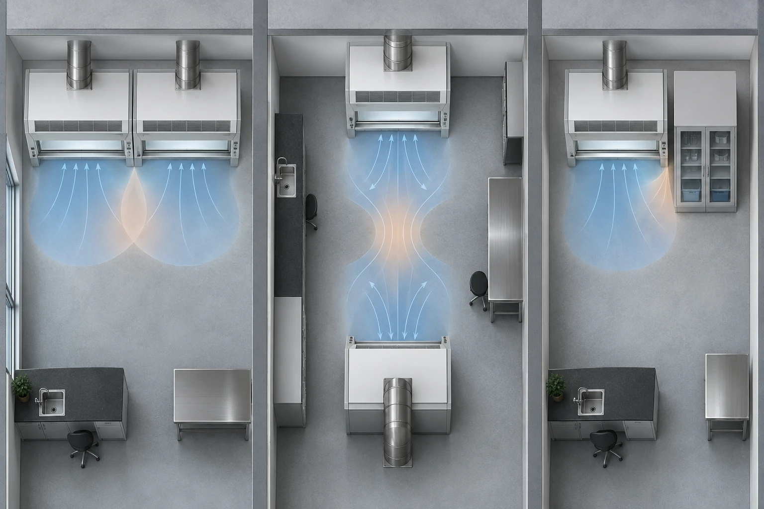
Two hoods placed near each other interfere, and the clearance that prevents it depends on how they face. A laboratory EHS standard states the mechanism plainly: hoods located immediately next to each other or immediately across from each other can create adverse effects on each other.
| Arrangement | Clearance | Source |
|---|---|---|
| Adjacent on the same wall, independently engineered | 40 in | Institutional design standard |
| On adjacent perpendicular walls, to the inside corner | 48 in | Institutional design standard |
| Facing each other | At least 5 ft | Institutional design standard |
| Facing each other | No less than 2.0 m (about 6 ft 7 in) | Institutional design standard, metric |
| Face to face, or a hood opposite a biosafety cabinet | At least 9 ft | Institutional EHS standard |
| Side to a wall or column projecting beyond the sash plane | At least 16 in | Institutional EHS standard |
| To large equipment, columns or similar obstructions | At least 3 ft | Institutional design standard |
The facing-hood values spread from 5 feet to 9 feet, and the reason is not carelessness. A pair of hoods facing each other across a bench share the air between them, and the shorter the gap the more each one draws from the other’s working zone. An institution that manages this with a 5-foot rule is accepting a tighter arrangement than one that requires 9 feet, and both numbers are visible in their own standards.
The lateral values spread as well, from 16 inches to 3 feet, because they measure to different obstacles. A column projecting past the sash plane sits closer than a block of large equipment, and the two clauses were written for those cases rather than for a single generic obstruction.
Choose the row that matches the arrangement rather than the smallest number in the table.
Hoods Facing Each Other and Hoods Facing a Biosafety Cabinet
The hardest arrangement to place is a hood opposite a biosafety cabinet, because the two units are designed to handle different hazards and neither one should be asked to make up for the other. An institutional EHS standard resolves it with a single rule: hoods are not to be installed face to face with another hood or opposite a biosafety cabinet unless the distance between them is at least 9 feet.
That clause protects two different working openings from each other. Air drawn toward one enclosure meets air drawn toward the other, and the space between them becomes the region where both lose stability. The 9-foot value is the largest face-to-face figure in this review, which fits the reasoning: the two units pull in opposite directions along the same axis.
Selecting a lower-draw enclosure is one way to reduce the interference a tight room can tolerate, and enclosures built for reduced exhaust volume are described in low-flow high-performance hoods. The physical separation still has to satisfy the clause that governs the room, so the equipment choice changes the exhaust demand rather than the clearance.
Storage Cabinets, Columns and Other Neighboring Equipment
Neighboring equipment matters when it changes the air near the hood or blocks the path of that air. A laboratory design guideline states that supplemental flammable or solvent storage cabinets are not to be located next to the hood superstructure, a restriction that protects both the cabinet and the hood because both draw air and both can be a fire source.
Columns and large equipment fall under the lateral clearance clauses, which range from 16 inches to 3 feet depending on the object. Cabinets that block or reduce the effectiveness of supply or exhaust air are prohibited separately, which catches the tall storage unit parked under a diffuser.
The pattern across these clauses is that equipment is judged by its effect on the air, not by its category. A hood moved along a wall to gain clearance from a column can lose its diffuser distance at the same time, so the four physical conditions should be tested together on the same drawing rather than one at a time.
Test the arrangement row by row before you release the wall, and you can decide whether a proposed pair of hoods and their neighboring equipment can share a room. A passing installation still leaves questions that placement requirements do not answer.
What the Placement Requirement Does Not Prove
Acceptance Criteria for Cross-Draft Velocity and How They Differ
A cross-draft limit is an acceptance criterion, so it is applied at test time to whatever the room happens to be delivering. SEFA 1 sets out how that limit is checked: a thermal anemometer and a smoke source are used on the space in front of the hood, and a measurement that breaches the ceiling is cleared up before the hood goes forward for its test. The same ceiling appears in a university standard, expressed as 30 percent of face velocity with 20 percent as the figure to aim for rather than the figure to pass.
The difference between the two structures is what happens as conditions change. A ratio ceiling tightens when face velocity falls, so the same room can pass at one hood setting and fail at another without anything moving. An absolute ceiling of 30 feet per minute in any direction at the hood face, as one federal manual writes it, behaves the opposite way and does not scale with the hood setting at all.
A third structure combines both: not above 50 feet per minute or 50 percent of face velocity, whichever is less. Applying the wrong structure passes installations that the governing document would reject, and the error is invisible in a report that records only the measured number.
A Passed Containment Test Does Not Clear the Location
A hood can pass tracer gas containment testing and still sit in a bad position. SEFA 1 states that although it may be possible to certify the hood based on tracer gas containment testing, excessive cross draft shall be disclosed in the test report.
That clause separates two different findings that commissioning paperwork often merges. The containment test answers whether the cabinet contains a challenge under the test conditions. The cross-draft finding answers whether the room delivers air across the face in a way that undermines that containment in service, and the standard requires the second finding to be recorded even when the first one passes.
The gap matters to whoever signs the report. A certificate with no cross-draft note reads as a clean bill for the location, while the standard that governs the test expects the draft to be written down whether it passed or not. Ask for the cross-draft record explicitly, and the location’s status becomes visible rather than implied. Test protocol details, including the test states and the tracer gas procedure, are covered in ASHRAE 110 testing.
Design Values Are Not Field Readings
Placement requirements are satisfied on paper and then re-measured in the room, and the two results are allowed to differ. A design target such as 5 feet from the plane of the sash is checked by looking at the drawing, while a cross-draft reading of 30 percent of face velocity is checked with an instrument at the hood face.
Field verification of cross drafts is a named test item rather than an optional extra, and the survey method is specified with its instruments: a thermal anemometer and a smoke source. Neither instrument appears in a drawing review, and no drawing review can produce the reading the standard asks for.
Keeping the two apart protects both. A drawing note cannot demonstrate that a room performs, and a field reading cannot show that a diffuser was drawn 5 feet from the sash rather than 4. When an inspection finds a problem, the type of evidence decides the remedy: a field finding points at the room as built, and a drawing finding points at the design it came from.
How Cross-Drafts Interact With Sash Height
Sash position changes how much a cross draft matters. SEFA 1 states that high cross-draft velocities are particularly detrimental to hood performance when vertical sashes are raised above the design operational height.
The mechanism is geometric. A raised sash presents a taller opening, more of the face is exposed to air arriving from across the room, and the same draft reaches further into the working zone. A hood that performs acceptably at its design opening can fail at the same room conditions once the sash is parked higher than intended.
Sash height has its own requirements, values and working-opening logic, so this page treats it as a stacking condition rather than as a placement rule. Those requirements are set out in sash height requirements. Placement sets the air that arrives, and sash position sets how much of the opening that air can reach, so a review that changes one should re-check the other.
Read a passed test for what it recorded, and you can decide which findings a report has established and which ones it has left open. Turning that judgment into a project document is the next step.
Fume Hood Placement Requirements: Project Review Checklist and Documentation Inputs
The Placement Review Table
A picture of a fume hood bay can look acceptable while three separate clauses fail on it. The table below compresses the four physical conditions plus the two room conditions into rows you can walk with a drawing, marking each position against the requirement that governs your project.
| Review item | Criterion and published spread | Measured to | Ask whom | Consequence of a failed row |
|---|---|---|---|---|
| Supply diffuser distance | At least 5 ft; 5 ft minimum, CFD or mockup may justify less; not within 4 ft 6 in; not within 10 ft for directional diffusers | Hood face, or plane of the sash | Mechanical designer | Diffuser relocation or a documented alternative study; a diffuser already cast into the ceiling becomes a change order |
| Supply diffuser direction and type | Never directed toward the hood or at an oblique angle; not directly above the hood; not below or adjacent to supply or exhaust vents; perforated low-throw rather than louver or nozzle; laminar rather than bidirectional registers | Diffuser discharge pattern across the hood face | Mechanical designer | Pattern change on the terminal, or relocation; a laminar terminal cannot be corrected by a distance dimension |
| Door distance | More than 10 ft as transcribed; 60 in face side and 40 in side panel between adjacent doors; at least 4 ft 6 in sash side and 3 ft side; at least 4 ft from adjacent doorways | Door or doorway to hood face, sash or side panel | Design team plus EHS for the governing clause | Hood relocation, or a project exception recorded with the governing document named |
| Clearance in front of the hood | At least 4 ft 6 in operator work area; about 36 in undisturbed zone; at least 6 ft to an opposing wall or obstruction | Hood face outward | Design team plus the laboratory manager | Bench or storage relocation before the room is fitted out |
| Workstation orientation | Openings not opposite workstations used all day; seated work stations not directly opposite openings | Line of sight across the opening | The laboratory manager plus EHS | Reorientation or swap of the workstation position; no distance satisfies these clauses |
| Adjacent hood and equipment clearance | 40 in same wall, 48 in to an inside corner; 5 ft to 9 ft facing each other; 16 in to a projecting column, 3 ft to large equipment; storage cabinet not beside the hood superstructure | Between units, or unit to obstruction | Design team plus EHS | Wall layout revision; seating two facing hoods closer than the governing figure cannot be corrected by control settings |
| Room pressure and make-up air | Designed negative to adjacent non-laboratory areas; harmful aerosols escape when the room is not negative | Room boundary | Mechanical designer | Balance and control revision, which is outside placement scope |
| Cross-draft field reading | Not above 30 percent of operating velocity, ideally 20 percent; or 50 ft per minute or 50 percent, whichever is less; or 30 ft per minute in any direction | In front of the hood face, at the working opening | Commissioning authority plus EHS | Draft source eliminated before the hood test continues |
Worked example. A 26 ft by 18 ft teaching laboratory with a 9 ft ceiling is being fitted with three 6 ft hoods along one wall, each rated 750 cfm at a 100 feet per minute face velocity. The door beside hood A sits 6 ft from the hood face. A ceiling diffuser sits 7 ft to the side of hood A, a directional diffuser sits 8 ft in front of and slightly to the side of hood B, and a third diffuser sits directly above hood B. Hoods B and C face each other across a 6 ft aisle, and the exhaust from the three hoods turns the room over at about 30 air changes per hour.
Run the rows. Hood A passes the diffuser distance row at 7 ft under the 5-foot values and also checks against 4 ft 6 in, and it needs 4 ft 6 in of operator zone, which the layout provides. Hood A fails the door row at 6 ft if the project is bound to the 10-foot transcription, and it passes if the project is bound to the two-tier figures of 60 in and 40 in; that call belongs to the design team with EHS. The directional diffuser 8 ft from hood B fails the 10-foot clause that applies to directional terminals. The diffuser above hood B fails outright, because a diffuser directly above the hood can create turbulence that carries contaminants into the room.
Change one condition and the answers move. Move the directional terminal to 11 ft and rotate it away from the hood, and that row passes while the terminal above hood B still fails. Widen the aisle to 9 ft and the facing hoods satisfy the clause that requires the largest separation; leave it at 6 ft and the pair satisfies the 5-foot and 2.0 m values instead, which means the outcome depends on which clause the project adopts rather than on the geometry alone.
Which Measurements the Review Requires
Two rows of the table cannot be completed from a drawing. Cross-draft velocity is verified with a thermal anemometer and a smoke source, and any draft above the limit is to be eliminated before the hood test proceeds; the survey that produces the number includes the measurement of cross-draft velocity as a named item.
A field check of this kind produces a reading for the room as it stands, so it belongs to the window after installation and before sign-off, and it can also be repeated later on a hood that has developed a complaint. Measurements taken during a bench survey answer what the room delivers now; they do not certify that the drawing was correct.
The third row that needs a live reading is room pressure, which is observed at a boundary rather than at the hood. Keeping the laboratory at a pressure below its neighbors is a design requirement, because aerosols that should stay inside can migrate into surrounding spaces wherever that relationship is reversed.
Documentation and Project Inputs to Assemble
A placement review moves faster when the inputs arrive together, and the same list serves an internal enquiry and a supplier enquiry. Gather the floor plan marked with hood positions, doors, operable windows and every supply and exhaust terminal; the hood list with sizes and design exhaust volumes; the name, edition and relevant clause of each document the project adopts, including the specification that names the standard the room is held to; any existing cross-draft or smoke survey; and the room air change rate, which becomes a placement input when it runs above 15 air changes per hour.
Two smaller items prevent avoidable exchanges. Confirm whether the room is designed negative to adjacent non-laboratory areas, and confirm whether the terminals are directional or general room diffusers, because that distinction decides whether the 10-foot clause applies.
How to Read a Failed Row
A failed row is a statement about which layer of the design owns the problem. A diffuser distance failure belongs to the mechanical layout and to whoever positioned the ceiling terminals, because a terminal can usually be moved at the cost of a ceiling revision. A door distance failure belongs to the room layout and to the design team’s reading of the governing clause, and it may be resolved by a recorded project exception rather than by moving the hood.
The layer also decides who has standing to settle the finding. A diffuser disagreement is closed between you and the mechanical designer; a door finding that turns on which clause governs needs EHS to confirm the institution’s own requirement rather than a code interpretation. Send each failed row to the party that owns its layer, and the review resolves without a general dispute about numbers.
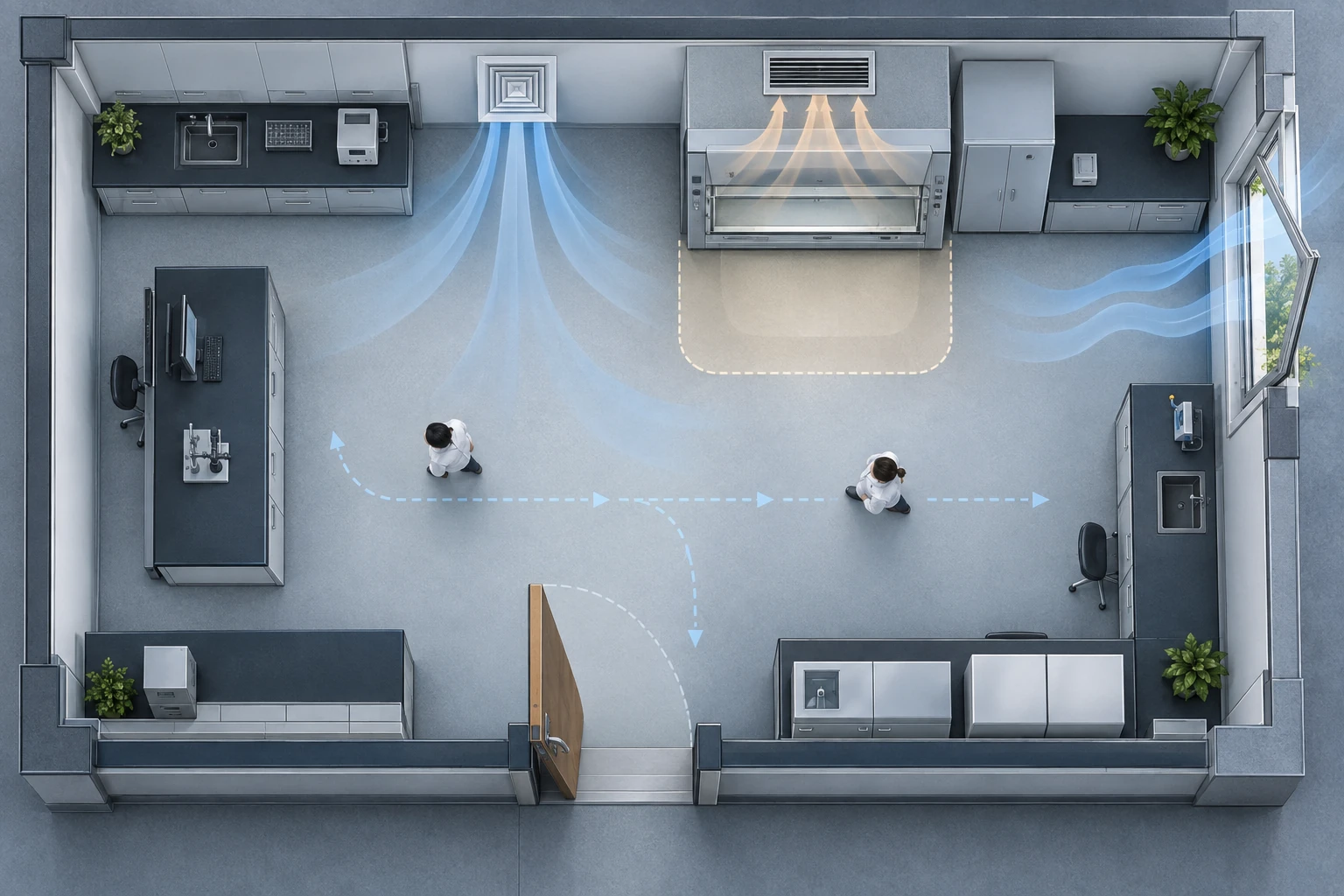
Mark the eight rows against one drawing, and you can decide what to correct, what to escalate and what to document as an accepted project condition. Where a row cannot be settled inside the project team, specialist review is the answer.
When Specialist Review Is Required
Conditions That Put the Decision Beyond the Project Team
A placement review can be closed inside the project team for most rooms, and there are conditions where it cannot. The most direct one is the clause itself: an institutional EHS standard directs design professionals to consult NFPA 45 section 7.9 regarding the placement of fume hoods within the laboratory, and where that standard is invoked by the specification, its interpretation is a specialist task rather than a reading of a table.
High air change rates are the second trigger. Institutional design standards note that where a laboratory runs above 15 air changes per hour, special air supply distribution systems may be necessary to keep containment from being affected by cross drafts. A room at that rate no longer sits inside the ordinary diffuser distance rules, because the supply pattern itself has to be engineered.
Where a standard distance cannot be met, the exception path needs technical evidence rather than a note. One institutional standard allows less than 5 feet between a diffuser and the plane of the sash only when further investigation justifies it through a CFD study or a physical mockup. Neither study is produced by the project team as part of a drawing review.
Two boundary conditions also leave the room. Exhaust discharge outside the building is constrained to avoid re-entry into the laboratory building or adjacent buildings at concentrations above 20 percent of the allowable concentrations inside, which puts part of the airflow question at building scale. Radiation, perchloric acid and explosive atmospheres each add criteria that may not be published in a design standard at all, and in those cases the authority having jurisdiction sets the terms.
The four conditions share a feature. None of them is answered by a more careful reading of a published distance, so continuing the internal review adds effort without adding certainty.
What to Bring to the Specialist
A specialist review runs on the record, so the package should carry the design intent and the constraint that prompted the request. Bring the floor and ceiling plans marked with hood positions, doors, windows and every supply and exhaust terminal; the hood schedule with cabinet sizes and design exhaust volumes; and the exact document editions the project adopts, including the specification clause that names the standard being applied.
Add the constraint in plain terms: which row of the review failed, which published figure it failed against, and which alternatives the design team has already considered. Where a standard distance cannot be met, state the alternative being proposed so the specialist can judge whether a CFD study or mockup is the right route, rather than commissioning a study that answers a question nobody asked.
Two further documents shorten the exchange. Include any cross-draft or smoke survey already performed, because a field reading tells the specialist what the room delivers now. Include the room air change rate and the make-up air strategy, since a room above 15 air changes per hour is judged as a supply distribution problem rather than a distance problem.
Assemble the package when a trigger condition appears, and you can decide to stop iterating internally and route the open item to the right specialist. From there the review goal is to keep the placement judgment observable after the project closes.
Related Products and Next Step
Equipment That Keeps the Placement Judgment Observable
A placement review produces a decision, and a decision about airflow is only as good as the readings that follow it. Once a hood is sited and commissioned, the face velocity it holds in service tells you whether the room conditions you accepted are still being delivered, which is why the visible instrument at the hood matters as much as the drawing note behind it.
| What the project needs | Why it follows from this page | Where to look |
|---|---|---|
| A hood family that matches the layout you were able to place | Facing hoods and short aisles limit how much exhaust volume a room can carry | Laboratory fume hood systems |
| A reduced-exhaust enclosure for tight rooms | Lower exhaust demand eases face-to-face and aisle constraints without changing the governing clearance | Low-flow high-performance hoods |
| A monitor that keeps the face velocity visible | Cross drafts and door traffic show up as a change in face velocity before anyone notices a smell | Fume hood airflow monitor |
None of those choices replaces the rows you reviewed. Equipment selection changes exhaust demand and observability, while the clearance clauses apply to whatever is installed.
What to Send Us
Tell us the room dimensions and the arrangement: how many hoods, which way they face, and how much aisle sits between them. Send the door and terminal layout with distances marked, because the two figures that most often decide a layout are the diffuser distance and the door distance.
Name the document your project follows, including its edition and the clause that covers placement. State the room air change rate, and say whether the supply terminals are directional or general room diffusers, since that distinction decides which distance applies.
Send anything you already have measured: a cross-draft survey, a smoke test record, or a face velocity log. A reading from the room shortens the exchange more than a description of it.
Further Reading on This Site
Placement is one condition inside a larger laboratory ventilation picture, and the pages that own the neighboring questions are worth reading in the order the project encounters them. Face velocity thresholds set the values that the placement ratios are calculated against, and face velocity requirements covers the acceptance values and their test conditions.
Supply air and pressure balance sit on the other side of the hood face, and makeup air and room pressure balance covers the volumes and control that placement deliberately leaves open. Where a room has to hold two facing hoods in a short aisle, fume hood versus biosafety cabinet covers how the two enclosure types differ in what they are designed to contain.
Fume hood placement requirements end where the room begins, and the room is the part you can still change on paper. Work the four physical conditions and the two room conditions in order, name the document that governs each one, and you can determine whether the position you sign off is one you can defend with a clause rather than with a habit.
Frequently Asked Questions on Fume Hood Placement
Does OSHA Set a Face Velocity Requirement for Fume Hoods?
The laboratory chemical hygiene rule is performance-based, and it carries no velocity figure, as the standards section above sets out. Face velocity thresholds belong to a separate article, so this page answers placement and points you to face velocity requirements for the values.
What Is the ASHRAE 110 Test Standard?
ASHRAE 110 is the tracer gas containment test referred to earlier, and its protocol sits outside the scope of this page. What this page needs from it is one conclusion: a hood that passes containment testing does not have its location cleared, which is set out in ASHRAE 110 testing.
How Does a Fume Hood Provide Protection?
The containment mechanism and how protection is designed and tested sit outside the scope of this page, and they belong to the equipment type and test pages. Position is what this page owns, and position is also what fixes the incoming air a hood has to cope with.
Leave a Reply