





Key Takeaways
- Geometry and operating position decide the walk in vs distillation fume hood choice, not vendor naming. A walk-in or distillation fume hood is a large enclosure without a standard benchtop, built so equipment taller than a person can sit inside it, and the one fact that separates the families is where the operator stands while the work runs.
- Measure the equipment and the loading route before any hood is named. The tallest, deepest and heaviest installed position drives the internal clearance you need, and the route that equipment travels to reach the hood is a project condition rather than an installation detail.
- A physically larger opening moves more air, so the hood decision is also a room-level decision. The bigger the open face, the more air the exhaust must move; sash form and operating position set the effective opening, and your make-up air and negative pressure cascade have to carry the result.
- Face velocity and working depth come from named institutions, not from one universal requirement. Recommendations published by the National Academy of Sciences set 80–100 fpm for chemical fume hoods, VCU’s program uses 80–120 fpm by hazard class, UCSC asks for at least 6 in of working depth and Rutgers for at least 4 in.
- Some numbers do not exist, and some sign-offs are not yours. No authoritative source gives a general clearance or lifting-load figure for these hoods, and no authoritative clause covers heat-load limits or utility layout, so you own the method while other professions own the values.
Procurement teams write “large fume hood” on a requisition and expect a bigger version of what they already own. Design teams inherit that line and start comparing product pages, where the same cabinet is described as a walk-in, a floor-mounted hood, a distillation hood or a high-boy depending on who wrote the page. The equipment that gets quoted is then chosen before anyone has measured the equipment that decides it.
A walk-in or distillation fume hood is a floor-standing enclosure built for apparatus that is taller than a person, so the working position and the loading route replace the benchtop as the organizing facts. Whether you specify a walk in vs distillation fume hood unit, the deciding question is the same one: does the operator stand outside the sash and reach in, or does the equipment itself need to travel inside the enclosure to be set up? Everything else in this article follows from that answer.
What Decides a Walk In vs Distillation Fume Hood Choice: Geometry, Not Terminology
A tall apparatus creates two separate problems, and vendors often describe them as one. The first problem is vertical: the equipment has to fit, which is a measurement. The second problem is positional: the work has to be carried out somewhere, either at a raised surface in front of the enclosure or at floor level inside it, and that is a decision about the task rather than about the cabinet.
The geometry check comes before any product name is used. Ask what the tallest installed position measures, what that apparatus weighs, and whether it arrives as one piece on wheels or in parts that can be carried and assembled at the aperture. Those three answers place your project in one geometric family, and the vendor vocabulary then becomes a labeling issue rather than a technical one.
Authors of laboratory design guidance make the same point from the other direction. One national consensus text on laboratory safety states that hood selection should follow the size of the apparatus and the way it is manipulated, because a cabinet chosen by its nominal footprint can be unsuitable for the work it is asked to contain. That principle is the reason this article spends its first module on judgment criteria instead of on a product taxonomy.
Types of fume hoods classifies the enclosures used across laboratory work, and this page does not repeat that list. Here the question is narrower: given one tall apparatus, which geometric family do you specify, and what evidence do you write into the record to defend the choice.
The One Difference That Decides It — Where the Operator Stands
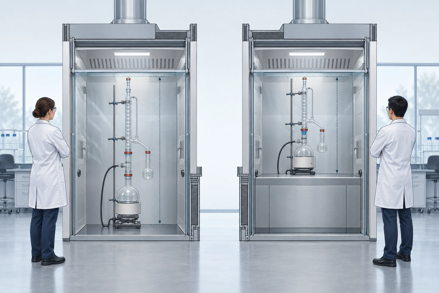
The decisive difference between the families is the working position. In one arrangement the operator stands outside the enclosure and works at a raised surface, reaching through the sash opening; the floor of the enclosure is not part of the working envelope. In the other arrangement the enclosure stands directly on the floor, the sash opening extends over most of the front, and the apparatus or the operator occupies the same floor the cabinet itself stands on.
That second arrangement is what people mean by a floor-mounted or walk-in enclosure, and it splits again into two cases that need to be kept apart. The first case is equipment that is rolled in and out, where a cart, a pallet truck or a solvent drum enters the enclosure and the person stays outside. The second case is an operator who steps inside to set glassware up and then works from within the enclosure. Both are physically possible in the same cabinet, and they are not the same requirement.
Keeping the two cases apart resolves most of the confusion in this topic. A specification that asks for a floor-level entry for carts does not thereby authorize people to stand inside the enclosure, and one vendor’s guidance on apparatus handling is often written for exactly one of these two cases. Read every product page with that question in hand, and contradictory statements stop being contradictory.
Six Vendor Claims About Walk-In, Floor-Mounted and Distillation, Side by Side
Vendor material is the loudest source of terminology in this topic, and the loudest sources disagree with each other. Five engineering-led pages on large laboratory hoods, all examined while preparing this article, describe the three terms in seven statements across six distinct positions. None of them is a standard, none of them carries a jurisdiction, and no authority has reconciled them. The table sets the statements out as statements, without picking a winner.
| # | Vendor claim | What the page says | What the geometry shows |
|---|---|---|---|
| 1 | Floor-mounted is the taller category | A floor-mounted hood is described as taller than a distillation hood | A naming hierarchy, not a measurement; neither term carries dimensions |
| 2 | Distillation hoods raise the working surface | A distillation hood is described as having a pedestal that elevates the work surface to a height of about 20 in above the floor | A raised-surface arrangement, which is the opposite of a floor-level loading position |
| 3 | Distillation hoods combine both traits | A distillation hood is described as having the height of a floor mount plus a conventional work surface | Consistent with a tall cabinet that keeps a front work surface at standing height |
| 4 | Floor-mounted means walk-in | The two terms are presented as equivalent names for one product family | True as vocabulary in many catalogs; says nothing about whether a person enters |
| 5 | Walk-in means floor-standing | The hood is described as floor-standing, and the same page advises against technicians walking inside | The enclosure geometry is floor-level while the operating position stays outside |
| 6 | The names carry history | Older floor-mount hoods were called walk-in hoods; the same account adds that nobody should work inside them, while equipment on carts is frequently pushed in | Separates equipment entry from personnel entry more cleanly than any other page reviewed |
| 7 | A hybrid sits between the two | A cabinet described as halfway between a bench hood and a floor mount, used for tall columns or bulky equipment that never needs to be wheeled anywhere | Names the criterion this page uses: whether the apparatus ever has to move sets the access requirement as much as its height does |
Statement 7 is the one to keep in view, because it identifies a third possibility rather than a third name. If equipment never has to be wheeled anywhere, the floor-level entry that makes a walk-in enclosure walk-in is not required by the work at all, and a cabinet with a high interior on some other support may be sufficient. Comparing the statements this way turns the terminology problem into the question that actually decides the purchase: does the apparatus move, and does a person move with it.
Every claim above traces to a vendor or an industry publication, which is why none of them can settle a specification. The authoritative side does address the vocabulary, and it answers a different question than the vendors do. A national consensus text on laboratory safety defines a walk-in hood by construction, as a hood that stands on the laboratory floor and is used for very tall or large apparatus, and then states that the word “walk-in” is a misnomer, because one should never actually walk into a chemical hood while it is operating and contains hazardous chemicals. An authority and a vendor can therefore both say “walk-in” and mean different things by it: the authority uses the term for the enclosure’s construction while ruling out the behaviour its name suggests.
That distinction is the one to carry into a specification. A floor-standing enclosure either reaches the floor or it does not, and an operator either steps inside it or does not; those two facts are measurable, and the disagreement among vendor pages concerns labels rather than measurements. Where a supplier cannot state in writing whether the enclosure reaches the floor and whether personnel are expected to enter it, the page was written for a different reader.
Reading a high clearance fume hood Listing Without Confusing It With a Benchtop
The term high clearance fume hood is the most common trap in this topic, because search results for it are dominated by benchtop models with an unusually tall interior. Cabinets in that class have more internal height above their work surface than a standard bench model, and they remain bench equipment: the cabinet still sits on a bench or a support frame and the operator still works at a normal standing surface. No dimension is offered for that extra height here, because none of the sources retrieved for this article establishes a bench-line standard to measure it against.
A taller benchtop cabinet solves only the vertical problem. It gives extra height above a work surface, which suits taller glassware and columns that can be lifted into place, and it leaves the loading position and the floor-level access question entirely untouched. A floor-standing enclosure solves both problems at the price of a much larger opening and the exhaust load that comes with it.
The practical test is to look at the floor line in the drawing rather than at the interior height in the specification. If the cabinet’s working floor is at 36 in or thereabouts and the enclosure sits on a bench, you are buying added interior height. If the working floor is the laboratory floor and the front opening extends down to it, you are buying a floor-mounted enclosure. Applying that test before you compare prices keeps a tall benchtop quote from being read as a substitute for a floor-level installation, and it keeps you from specifying a benchtop cabinet with added height for work that has to be rolled in.
Before you move on to measurement, you can state this family selection in one sentence and defend it: the work fits within the internal height you must provide, and the operating position is either outside the sash or at floor level inside the enclosure. One condition keeps that sentence valid: it is written against one apparatus and one way of placing it, so if the tallest item changes or the apparatus stops being movable as one piece, the classification has to be established again rather than carried forward.
Measure the Equipment and the Loading Route First
Clearance failures are usually measurement failures rather than product failures. A specification that names a cabinet before anyone has measured the tallest installed position, the weight on wheels and the narrowest point on the route will be defended with opinions instead of numbers. The sequence matters more than the arithmetic: you decide the required internal envelope, then you confirm the equipment can physically arrive, and only then do you compare enclosures.
The reason the route belongs in this module rather than in an installation checklist is that it can invalidate an otherwise correct selection. An enclosure that satisfies every dimensional and airflow requirement is worthless if the apparatus cannot reach it. Design guidance from research institutions treats door widths, corridor turns and service access as project conditions that constrain equipment choices before installation begins, which is the same logic applied to a column or a reaction skid.
This module produces two things you will reuse in every later section. The first is a measured envelope with a defensible allowance on each axis. The second is a written record of how the apparatus will travel to the enclosure bed, including the bottleneck that limits it. Both belong in the project record, and both will be requested again when someone reviews the airflow numbers later in this page.
The Equipment Read-Out You Must Have Before Any Hood Is Named
Take five measurements on the largest configuration you will ever install, not the configuration you expect on day one. Record the overall height including condensers, columns, drying tubes and any instrument that rides on top; the depth from the rear of the largest item to the front of the widest fitting; the width across the widest traverse, which for a multi-neck assembly is usually wider than the vessel itself; the mass of the heaviest single item that enters the enclosure; and the height and mass of the assembly as it arrives, before any part is removed.
The distinction between installed height and arrival height decides how much of the enclosure you will actually be able to use. An apparatus that fits when assembled and cannot be carried through the opening when assembled has to be built up inside the enclosure, and that changes what the operator needs room to do. Write both figures down separately, because a single number invites the assumption that the tallest configuration can be carried in whole.
Treat the interior envelope as the equipment measurements plus allowances you can defend in writing. Hanging services, a vent line that must rise above the tallest vessel, a stirrer motor that sits on top of the assembly, and the movement needed to connect glassware all consume volume that the equipment itself does not occupy. The allowance you grant is a judgment call rather than a published value, and the next subsection explains why that is, and what to do about it.
Vertical and Horizontal Clearance: What to Measure, and Where the Numbers Do Not Exist
There is no authoritative general figure for the internal clearance a floor-mounted hood should provide, and no authoritative lifting-load figure for mounting an apparatus at height inside one. Forty-one candidate sources were retrieved and assessed while preparing this page, including national guidance, regulators, university design standards and a manufacturer’s engineering manual, and none of them publishes such a value. The absence is the finding: any number presented as the required clearance for this class of hood is someone’s working assumption, not a cited requirement.
What the authoritative sources do give is a principle and a set of conditions. A national consensus text on laboratory safety treats the enclosure as a system whose performance depends on how the apparatus is arranged inside it and how the work is performed, which is why an allowance has to be justified for the specific installation rather than copied from a catalog. One institutional design guideline, for instance, requires clear egress width in front of a hood rather than around it, a condition on the room rather than on the cabinet.
Write the allowance as a defensible calculation instead of borrowing a figure. A workable pattern is to take the tallest installed height, add the vertical space the highest connection needs, add the space the operator needs to make and break that connection, and state each addition with its purpose in one line. The result may not be the only correct answer, but it can be checked, challenged and revised, and a number that cannot be traced to a requirement will be the first thing removed when a project is reviewed for cost.
The Loading Route Is a Project Condition, Not an Installation Detail
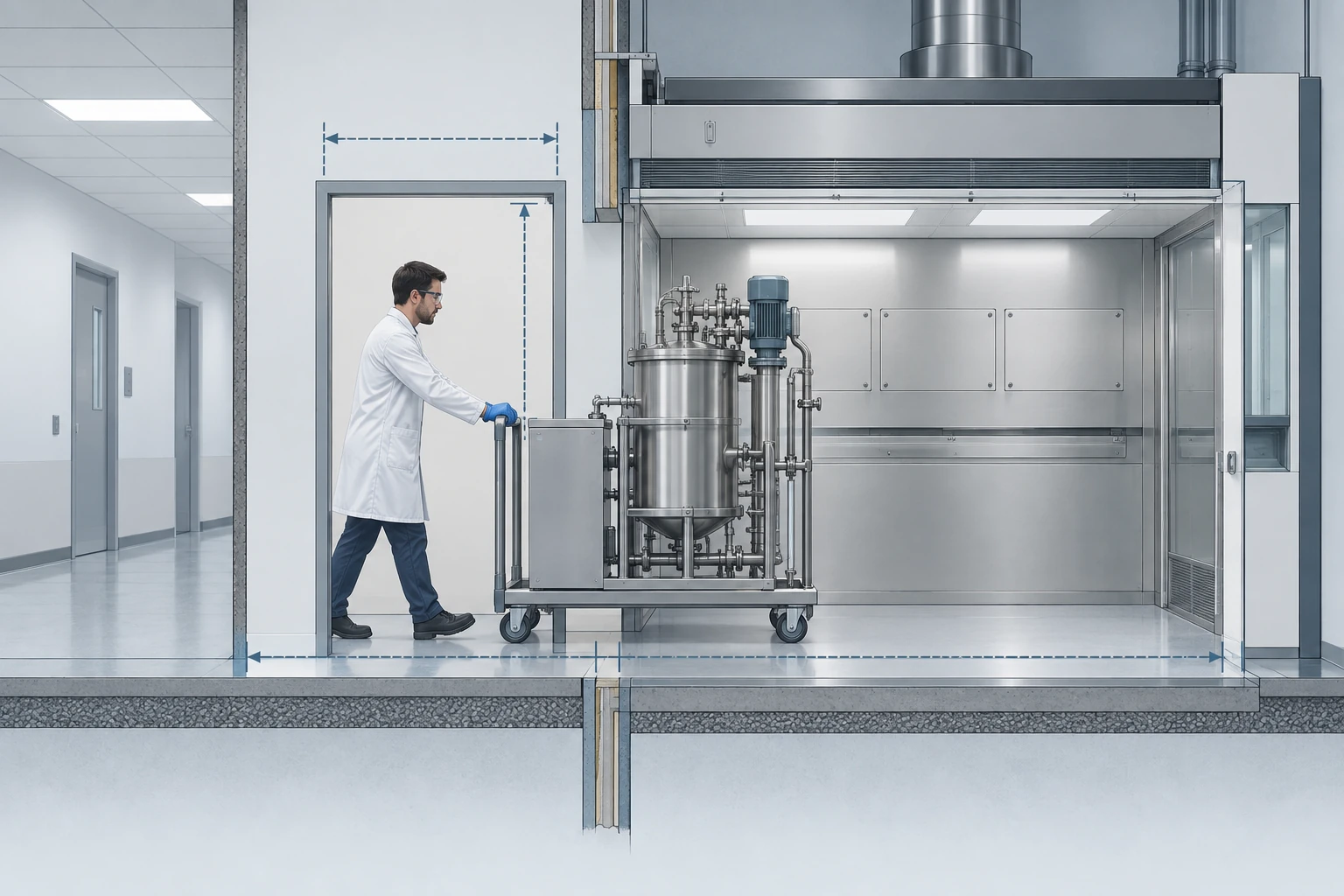
The route is measured in the same sitting as the equipment, because the two answers constrain each other. Measure the clear width of every door the apparatus passes, the clear width and turning envelope of each corridor or landing, the internal dimensions and rated capacity of any lift, the weight limit and the surface condition of the floor along the path, and the clear height of every opening, including pipework and door closers that reduce it. The narrowest figure on that list, not the average, sets what can be moved.
Equipment handling in this class of enclosure is a documented concern rather than a theoretical one. One engineering guide on floor-mounted hoods devotes a section to rolling drums, mobile processing skids and packed columns directly into the enclosure, and specifies a floor flush with the surrounding laboratory so that a lip or sill does not create a tipping hazard for a heavy drum. That is a vendor’s engineering position on how its own hoods are loaded. The construction that accepts this kind of entry, including the floor-mounted and walk-in enclosure itself, is specified rather than improvised, and the choice between a bench-line cabinet and a floor-level one is a different decision from the one on this page.
Two consequences follow. First, a route that cannot be opened up permanently changes the design premise, because an apparatus that can only enter once may still be impossible to remove for service; if it cannot be removed, the maintenance plan has to accept working around it and the enclosure has to be specified around that constraint. Second, the floor detail is a construction item with a cost and a sequence, so the floor finish, the ramp and the containment arrangement should be described in the same document as the cabinet rather than arranged after the cabinet is ordered.
Deciding the enclosure on this evidence is a short step. Put the measured envelope and the loading record side by side, and the family is determined: full-height loading access, a flush floor and a route wide enough for the largest item point toward a floor-level enclosure, while equipment that is carried in and set up in position keeps the floor-level access question open. Where the real question is whether the work belongs on a bench at all, benchtop versus floor-mounted hoods carries that comparison, and this page takes the floor-mounted premise as settled and moves on to the enclosure’s own dimensions.
How a Walk In vs Distillation Fume Hood Choice Moves Your Exhaust Load
Every enclosure removes contaminated air, but the volume it must remove is set by two things the geometry decision has already fixed. The first is the area of the opening that is left open during work. The second is the air speed you require across that opening. Exhaust volume rises when the opening grows even if the required speed stays the same, so the family you selected in the first two modules has already committed the laboratory to an airflow range before any duct or fan has been discussed.
A physically larger opening moves more air, and that single relationship turns one cabinet choice into a room-level decision. Large floor-standing enclosures have been built for decades, and published descriptions of them note that they need much more air than a bench hood and are normally run with the vertical sash closed. That is the design logic in one line: the opening is limited on purpose so the exhaust volume stays inside what the building can supply and remove.
This module settles the exhaust consequences that follow from your geometry choice, without entering fan or duct sizing. Decide the sash form and the operating position first, state the face velocity and depth you are adopting, name the institution behind those values, and then confirm that make-up air and the room pressure relationships can absorb the load.
Why a Larger Opening Demands More Air, and What That Does to the Room
Exhaust demand is the product of open face area and face velocity, and the result is expressed as a volumetric flow. A bench-line cabinet with a modest vertical sash presents a limited face. A floor-level enclosure with a front opening that extends down to the floor presents a far larger one, and it presents the largest face of all when the sash is fully open. The flow required to hold the same speed across that opening is correspondingly larger.
Industry engineering descriptions of large floor-mounted hoods put the required exhaust in the low thousands of cubic feet per minute during normal operation and note that the figure depends on sash position and must be calculated for the specific installation. That is a vendor’s engineering estimate rather than a cited requirement, so it is useful as an order of magnitude and useless as a specification figure. What it establishes is the scale: this class of enclosure is a major exhaust consumer relative to the cabinets most laboratories already run.
The consequence lands on the room rather than on the cabinet. Air that leaves the enclosure has to be replaced, the laboratory has to keep drawing air from the corridor so contamination travels inward, and the building has to remove what the laboratory exhausts. Institutional laboratory guidance is explicit that a hood requires make-up air to function and that the laboratory must hold a negative pressure relative to surrounding spaces. When the open face is large enough, an improperly managed sash will consume the available make-up air and disturb those relationships.
This is why a floor-mounted enclosure should not be evaluated as a purchase in isolation. Its operating position changes the building’s air balance, and any later reduction in make-up air capacity reduces how far the sash can safely be opened. Room pressure and make-up air are covered by other pages on this site, and the section below stops at the point where the mechanical design begins.
Face Velocity and Working Depth: Named Institutions, No Single Requirement
Face velocity is widely quoted as though one number applied everywhere. The sources that actually publish numbers do not agree, and each figure belongs to the organization that adopted it. The most authoritative statement found for this page comes from a national consensus text on laboratory safety, which says plainly that there are no regulations specifying an acceptable face velocity, and adds that face velocity is only one indicator of hood performance and should not be the sole basis for determining a hood’s containment ability. The table records that statement alongside the numeric values used while preparing this article, and gives the condition attached to each one. No single value in it is a universal requirement, and the differences between them are real rather than editorial.
| Value | Source | Condition attached to it |
|---|---|---|
| No regulation specifies an acceptable face velocity | National Academy of Sciences, *Prudent Practices in the Laboratory* | The consensus position: no regulatory threshold exists, and face velocity is one indicator among several rather than the sole basis for judging containment |
| 80–100 fpm recommended for chemical fume hoods | Same source | Professional-body recommendation for chemical fume hoods generally |
| 100–120 fpm | Same source | Described as historically recommended where very high toxicity or external disturbances affected performance, not as a current universal figure |
| Minimum average effective face velocity of 100 fpm, with a minimum of 70 fpm at any point | Stanford University laboratory standard and design guidelines | An institutional design requirement expressed as an average across the face plus a floor value at any single point |
| 100–150 fpm | University of California, Berkeley environmental health and safety program | The institution’s stated satisfactory range for its own hoods |
| 100 fpm at the sash | University of Kentucky occupational health and safety program | An average capture velocity at the sash, stated by one institution |
| 80–120 fpm | Virginia Commonwealth University environmental health and safety program | Stated by one institution as its range according to laboratory chemical hazard class |
| Working depth of at least 6 in | University of California, Santa Cruz environmental health and safety | Hands and apparatus kept behind the plane of the hood face while working |
| Working depth of at least 4 in | Rutgers University laboratory fume hood program | Same working-depth principle, published with a different figure across the hood |
| 36 in of clear aisle in front of the hood | Stanford University laboratory standard and design guidelines | An egress and access condition placed on the room, not on the cabinet |
One attribution that circulates widely is worth separating from the sourced values. Vendor and industry pages that cite a national occupational safety regulator for a range of roughly 60–110 fpm are not supported by that regulator’s own laboratory safety guidance on chemical fume hoods, which was retrieved in full while preparing this article and contains no numeric face-velocity range at all. The value may well be a defensible engineering target, but it does not carry the authority those pages assign to it, and a specification that rests on the misattribution will not survive a review.
Two further points keep the table usable. Face velocity and working depth are different requirements: the first constrains how much air moves across the face, the second constrains where the operator’s hands may be. Sash height requirements and face velocity requirements work through each of them in detail, and this page only fixes which values are admissible and how each one must be attributed.
The published values come from the organizations that adopted them: the National Academy of Sciences laboratory safety text for the 80–100 fpm recommendation and the historical 100–120 fpm figure, and the occupational safety regulator’s laboratory fume hood quick facts for the general positioning that the enclosure is a primary engineering control. Reading the second document is the fastest way to confirm what it does and does not say about airflow.
Sash Strategy, Make-Up Air and the Negative Pressure Cascade
The sash form is the cheapest control over exhaust load, and it is usually decided after the cabinet instead of with it. Before the mechanical design is finalized, decide three things and write them into the same document as the cabinet: whether the enclosure has a vertical sash, horizontal sliders or a combination; what the maximum open area will be during normal work; and who is permitted to change that position, and how the position is marked. These three answers are what the airflow calculation is built on.
The opening then has to be lived with. Institutional guidance on hood use asks that the sash be kept as low as the task allows, with the operator’s face outside the plane of the opening and the work performed well behind it. Large enclosures make that discipline harder to sustain, because the reason someone bought a floor-level cabinet is usually that tall apparatus has to pass through the opening. The practical resolution is a loading position and a working position that are not the same: fully open for the minutes the apparatus or the drum is moving, closed down to the marked operating position for the hours the process runs.
Make-up air is the constraint that decides how far this can go. A floor-level enclosure that demands several times the airflow of a bench cabinet will pull that air from the surrounding laboratory, and the laboratory pulls it from the corridor. If the make-up systems cannot supply what the enclosure removes, the room loses its inward pressure relationship, and air movement at the hood face becomes unstable in a way that no face velocity set point can correct. That is why the make-up air capacity belongs in the decision record before the cabinet is ordered.
Deciding this module’s output is straightforward once the numbers are attributed. You can now state the sash form and maximum open area you will accept, the face velocity and working depth you are adopting with the institution behind each value, and the make-up air and pressure relationship the room must sustain; the fan, duct and airflow calculations that follow are worked through in exhaust fan sizing, duct sizing and airflow calculation. One condition limits that conclusion: the relationship between a larger opening and a larger exhaust requirement assumes the room’s air can follow the opening, and it stops being predictable once make-up air is fixed rather than variable or when the enclosure shares its exhaust with other equipment.
Service Connections, Heat Load and Fire Protection Without Casework
A floor-level enclosure removes something that most laboratory specifications quietly depend on: the casework beneath the work surface. Services arrive through that casework in a conventional laboratory, and the bench itself provides the mounting surface for valves, sockets and gauges. Take the bench away and every one of those connections has to find a new route, which is a design task rather than an accessory choice.
Two of the three subjects in this module have no authoritative clause behind them, and saying so is part of the deliverable. No source examined while preparing this article states a maximum heat load for this class of enclosure, and none prescribes how water, gas, vacuum or electrical services should be arranged on a benchless enclosure. The third subject carries real regulatory weight, and it is also the one where the published standards cannot be quoted because their text was not obtained. This module therefore gives you a structure for each decision, and marks clearly which parts you write and which parts another discipline signs.
The pattern to adopt is to treat connections and heat as design inputs that you document, and fire protection as a scope decision that you route to a specialist. Deciding which is which, and writing the boundary into the specification, keeps a later review from turning an open question into a claim you never made.
Without a Bench, Utilities Go Outside or Through the Side Posts
Services on a benchless enclosure are mounted on the enclosure itself rather than on furniture. The arrangement described in vendor engineering material for these hoods places the service modules on the exterior side posts, or on a panel at the front of the enclosure, with the connections made to the building services from outside the working volume. Services that would have been hidden inside base cabinets are visible and reachable, and their routing has to be worked out with the trades that supply them.
The design consequence is that the utility layout becomes an elevation drawing rather than a plumbing detail. Every valve, outlet and gauge occupies a position on a post or a panel, and each one has to be placed where the operator can reach it while the sash sits at its operating position, without a service body standing in the airflow across the face. Items that intrude into the opening disturb the airflow the enclosure depends on, so the layout has to respect the face rather than the convenience of the installer.
Three items belong on a checklist for this part of the design. First, the list of services and their capacities, written before the enclosure is ordered, because a post can only carry what it was specified to carry. Second, the routing of each service from the building connection to the enclosure, including whether it runs overhead, along a wall, or under the floor, since a floor-level enclosure that must be loaded through the front cannot have a service trench crossing its aperture. Third, the location of shut-offs reached without entering the working volume, which matters when the enclosure is larger than the person using it.
Because the arrangement of services on this class of enclosure has no authoritative published requirement, the specification should name the party who will confirm the layout. That is normally the process or project engineer, with the enclosure supplier confirming what the posts and panels can physically accept. Writing that split into the document is what turns an unresolved layout question into a project decision, and it is also what allows the utility drawing to be issued without waiting for the rest of the enclosure specification.
Heat Load: an Item You Can Write, Not an Item You Can Limit
A distillation enclosure concentrates a heat source inside a space designed to move air. The apparatus under distillation releases heat through the vessel, the condenser and the connecting glassware, and the enclosure’s own airflow is what removes that heat from the working volume. The interaction matters because a hot surface changes how the air moves inside the enclosure, and it also matters to the materials and the containment arrangement around the apparatus.
No authoritative limit for the heat load inside this class of enclosure was found while preparing this article. The same body of evidence assessed earlier for clearance requirements was searched for a maximum heat input figure for floor-mounted hoods and for their working volumes, and none publishes one. That absence is why the specification cannot borrow a number, and it is also why a supplier who offers one should be asked for the basis of it.
What can be written is the way the number will be established. State the heat input of each source, in the unit the equipment is rated in, with the condition under which it runs, and state the airflow the enclosure is designed to pass; then have the calculation done by the party who owns the mechanical design. Where an open flame is part of the process, the flammables in the working volume need a separate look, because laboratory practice generally discourages open flame in an enclosure while flammable liquids are present, and the handling of those liquids is governed on its own axis by OSHA 29 CFR 1910.106 rather than by the enclosure’s specification.
The practical value of writing heat load this way is that it stops two common failures. One is the specification that quotes a maximum heat load that nobody can trace, which falls apart at review. The other is the specification that omits heat entirely, which produces a surprise when the apparatus runs hot. Stating the inputs and naming the party responsible for the calculation avoids both, and it costs no more work than quoting a figure would.
Fire Protection: Written as Scope and Sign-Off, Never as Clause Quotes
Fire protection for a floor-level enclosure holding a distillation process is a design scope, not an accessory. Where large volumes of flammable solvent are involved, standard building sprinklers are often described in industry material as insufficient for the enclosure itself, and dedicated suppression arranged inside the enclosure is discussed instead. That is an industry engineering argument rather than a requirement, and the decision it supports belongs to a fire protection specialist, working with the local authority that will review the installation.
The set of standards that bear on this scope can be named, and only named. NFPA 45 is the standard on fire protection for laboratories using chemicals, so it is the document that governs this class of laboratory space. NFPA 30 is the flammable and combustible liquids code, and it applies where those liquids are stored and handled, which for a distillation enclosure means it is part of the same decision. If a clean agent suppression system is selected, NFPA 2001 governs that system’s design and installation. The texts of these standards were not obtained while preparing this article; naming them identifies the applicable scope, and no clause, threshold or design detail can be quoted from documents that were not read.
Two related standards deserve the same treatment. ASHRAE 110 addresses how the containment performance of a fume hood is tested, which is how a claim about enclosure performance is verified rather than asserted, and its method is treated in ASHRAE 110 fume hood testing. ANSI/ASSP Z9.5 covers laboratory ventilation, and it sets the system context in which an individual enclosure operates. Both are identified here as scope references only.
For sites where the classification extends beyond flammable liquids, the construction requirements that follow from a hazardous location classification are a separate subject, and explosion-proof fume hood requirements works through what that classification changes. The general installation conditions that apply to a hood of any class, and the additional items this enclosure adds to them, are set out in fume hood installation requirements; this module only adds the benchless connection, heat and suppression items.
You can now assemble the third part of your decision record. The table collects the three subjects of this module with the item that has to be confirmed, the party who owns it, and whether any authoritative clause exists for it, so the open items are visible in one place rather than carried in prose.
| Item | Who confirms it | Is there an authoritative clause? |
|---|---|---|
| Service list with capacities, and the utility routing on the external posts or panels | Project engineer, with the enclosure supplier confirming what the posts and panels accept | No — no retrieved source prescribes how these services are arranged on a benchless enclosure |
| Position of valves, outlets and gauges relative to the working position and the face | Project engineer, with the enclosure supplier | No — the placement has to be judged against the airflow at the face rather than cited |
| Heat input of each source with its operating condition | Project engineer supplies the inputs | No — no retrieved source sets a maximum heat load for this class of enclosure |
| The heat load calculation and its consequences for airflow or materials | Mechanical engineer of record | No — the method is yours to document and defend |
| Where open flame is used, and the flammable liquids present in the working volume | Safety officer, with the fire protection specialist | Flammable liquid handling is regulated separately under OSHA 29 CFR 1910.106 |
| Whether suppression inside the enclosure is in scope, and its design basis | Fire protection specialist, with the authority that reviews the installation | Standards identified by number only: NFPA 45, NFPA 30, NFPA 2001; their text was not obtained, so no clause is quoted |
| Construction consequences where a hazardous location classification applies | Electrical and safety engineering, by classification | Handled separately; see the explosion-proof requirements page linked above |
One condition governs the whole table: the design inputs it records are validated against the enclosure you are buying, so a change of apparatus, of enclosure supplier or of the room’s air handling makes the affected rows provisional until they are confirmed again against the new configuration.
Working Position, Airflow Under the Load and Maintenance Space
Where a person stands is the decision the whole comparison turns on, and it is also the decision most often left implicit. The working position determines what the operator can reach, how far their hands travel beyond the plane of the opening, and what has to be moved out of the way when the process runs. It also determines what the enclosure must be able to do around the apparatus, because the space under and behind the load is where the enclosure’s airflow is collected.
This module closes the geometry arguments by turning them into conditions. It sets out the two working positions as a choice with consequences rather than a preference, explains why raising the apparatus off the enclosure floor matters to airflow, and states the access that cleaning and service will require. The boundary with other articles is deliberate: cleaning frequency and inspection methods are covered by the site’s inspection material, and the material comparison for linings and ductwork belongs to a separate page.
The output of this module is a small set of conditions you can add to the enclosure specification. Each one can be checked by looking at a drawing rather than by reading a narrative, which is what makes them useful at review.
Working at Floor Level or at a Raised Surface: the Trade the Vendor Names Hide
The two working positions differ in a way that can be read off a drawing. A raised-surface enclosure keeps a work surface in front of the operator at standing height, so the operator reaches forward and down into a working volume above that surface. A floor-level enclosure has no such surface: the working floor is the laboratory floor, and the operator either reaches into a tall volume or works at apparatus standing on that same floor.
Working at floor level has real consequences that a specification should acknowledge. Glassware assembled at floor height is assembled away from eye level, the operator’s reach into a deep enclosure is limited by the opening rather than by the cabinet’s internal volume, and a spill or a breakage happens at floor level where it is harder to see and reach. These are the reasons institutional hood guidance in general tells users to keep their faces outside the plane of the opening, keep work well behind that plane, and avoid entering the working volume, and they are also why one vendor’s own page on these hoods advises against working inside them at all.
Working at a raised surface inside a tall enclosure trades those problems for a different one, which is where the apparatus has to live. A raised surface that spans the enclosure reduces the height left for equipment, so an enclosure with a raised working surface and an enclosure with a floor-level working surface hold different apparatus for the same external height. That is the actual trade the vendor names obscure: neither arrangement is a better version of the other, they are answers to two different questions about where the work is done.
The decision rule follows from the work rather than from the enclosure. Decide the working position first, then let it decide whether a raised surface is present at all, and only then check the internal height against the equipment measurements from the earlier module. When the work is manipulation at the front of an apparatus, a raised surface keeps the operator’s hands and eyes where they are useful; when the work is setting up a tall assembly once and running it, a floor-level working surface keeps the maximum height available for the apparatus itself.
Keeping Airflow Under a Large Apparatus
An enclosure collects contaminated air through openings at its rear and along its lower edges, and the path those air streams take depends on what is standing in the way. When a large item sits flat on the enclosure floor, it blocks the lower part of that path, and the air has to find its way around the obstruction. Guidance on using this class of enclosure addresses the point directly by asking that large items be placed on blocks or stands so that air can move around and underneath them.
The reason this matters more in a large enclosure than in a bench cabinet is the size of the objects involved. A floor-level enclosure may hold a vessel, a column and a support structure that between them occupy much of the plan area, and each of those items can obstruct the lower exhaust slots if it is placed without thought. Raising the load restores the crawl space under it, which is what allows the enclosure to draw from the full height of its opening rather than only from around the apparatus’s shoulders.
The condition to write into the specification is a clearance under the load rather than a construction method. State that the apparatus is to be supported clear of the enclosure floor on a stand, deck or containment arrangement that leaves a gap under and behind it, and assign the support’s design to the party who owns the apparatus or the enclosure, depending on how it is procured. Where the enclosure is supplied with a floor-level containment arrangement, that arrangement becomes part of the same decision, because it changes the height the apparatus sits at. The comparison between enclosure materials, including what linings and floors resist, is treated in FRP versus polypropylene hoods and is not repeated here.
One limit should be stated alongside the condition. Raising an apparatus lowers the headroom left inside the enclosure, so the stand’s height is part of the internal height budget from the earlier module rather than an addition to it. A specification that adds a stand late in the process can consume the allowance that made the enclosure suitable in the first place, which is why the support arrangement belongs in the same drawing as the apparatus dimensions. The comparison below therefore holds only while the stand height stays inside the allowance: once the support and the apparatus together exceed the internal height you measured, the working position has to be reconsidered rather than the stand adjusted.
Cleaning, Servicing and the Space That Must Stay Clear
Interior surfaces in this class of enclosure have to be cleanable across the full working volume, which is a requirement on the enclosure and a condition on the room. The enclosure side of it is surface finish and construction, including corners and junctions that can be reached and washed. The room side of it is access: a floor-level enclosure is serviced from the front, and cleaning or repairing the rear of its interior means either reaching across the whole working volume or moving the apparatus aside.
Service access is therefore a dimension to protect rather than a habit to encourage. Leave the front of the enclosure clear to the full width of its opening and to the depth needed to open the sash fully and work in front of it, keep the area under and behind the apparatus reachable for cleaning, and keep any panel, service post or control that requires periodic attention free of stored equipment. The point of writing these conditions down is that they are the first things lost when a laboratory runs out of bench space, and once lost they are difficult to recover.
Inspection and maintenance schedules for a hood are covered by the site’s general material, and the additional item this class of enclosure brings to that list is access rather than frequency. Fume hood inspection checklist sets out what is examined and how often; what a floor-mounted enclosure adds is the need to check that the access it needs has survived the laboratory’s other changes, because equipment tends to accumulate in front of a large enclosure rather than inside it.
You can now add working position, under-load clearance and protected access to the specification as three checkable conditions. The table sets the two working positions side by side with what each one commits you to, so the choice can be made against your process rather than against a product name.
| Raised working surface inside the enclosure | Floor-level working surface | |
|---|---|---|
| Where the operator works | At a surface at standing height, reaching into the volume above it | At the laboratory floor, reaching into a tall volume or working on apparatus standing on that floor |
| Handling of the apparatus | Lifted or assembled onto the surface | Rolled, carried or assembled at floor level |
| Internal height available for apparatus | Reduced by the surface and by whatever stands on it | The full internal height of the enclosure |
| Airflow under the load | The surface itself forms the lower boundary; openings under it must be kept clear | Depends on the support arrangement; the gap under the load has to be specified |
| Typical fit | Manipulation at the front of an apparatus, with the operator’s hands and eyes where they are useful | Setting up a tall assembly and running it, where maximum height matters more than a surface |
| Main exposure to watch | The apparatus gets less vertical room than the enclosure’s external height suggests | Assembly, spills and breakages happen away from eye level |
A reviewer can confirm each condition from the general arrangement drawing, and the airflow and maintenance consequences of the choices are visible before the enclosure is ordered rather than after it is installed.
Run the Six-Step Decision, and Read the Worked Example
The preceding modules each settled one part of the comparison. This module runs them in the order in which they have to be decided, because the order is what separates a defensible selection from a plausible one. Each step uses the output of the step before it, and each step ends with something written down rather than something remembered.
Two properties of the sequence are worth stating before the table. The first is that no step can be skipped: a decision taken at step one is invalidated if step six turns out to be impossible, which is the failure this order is designed to prevent. The second is that the sequence is checkable. Every row in the table below produces an artifact that someone else can read, question and approve, and a selection that has no such artifacts is an opinion.
The sequence is drawn from the decision spine set out in this page’s planning, and the worked example that follows applies it end to end to one project so the outputs can be seen in a single place.
The Six Steps in Order, With the Criterion at Each Step
| Step | Input you need | Criterion that decides it | Output you write | Who confirms it |
|---|---|---|---|---|
| 1 Measure the equipment | Tallest installed height, depth, widest traverse, heaviest single item, arrival configuration | Does the apparatus fit the enclosure with the working position you intend, allowing for services, connections and the movement to make them? | A measured envelope with a stated allowance on each axis | Project engineer |
| 2 Decide the working position | Whether the operator reaches into the work or the apparatus is only moved into place | Is the work manipulation at the front of an apparatus, or setting up and running a tall assembly? | Working position stated as raised surface or floor level | Process owner with safety review |
| 3 Fix sash form and opening | How the apparatus enters and how the process runs | What is the largest open face during normal work, and who may change it? | Sash type, maximum open area, marked operating position | Mechanical engineer of record |
| 4 Check exhaust and make-up air | The result of step 3, plus the room’s make-up air capacity | Can the make-up air and the room’s inward pressure relationship carry the resulting exhaust without losing stability at the face? | Adopted face velocity and depth, with the institution behind each, and the make-up air requirement | Mechanical engineer of record |
| 5 Confirm services and heat | The service list, its capacities and the process heat release | Are the utilities routed and confirmed against the chosen geometry, and is the heat input written with a party assigned to calculate it? | Utility layout and a heat statement naming its owner | Project engineer and mechanical engineer of record |
| 6 Verify the loading route | Door and corridor clearances, lift capacity, floor condition, turn geometry | Can the apparatus arrive, and can it be removed later for service? | A route record with the governing bottleneck dimension | Project engineer, with facilities |
Reading the table in order shows why the enclosure cannot be selected first. Step 3 depends on step 2, because the working position decides how much of the opening has to be usable during work rather than only during loading. Step 4 depends on step 3, because face area and face velocity together produce the exhaust volume. Step 6 depends on nothing above it and can invalidate all of them, which is the reason it is checked rather than assumed even when the apparatus is already on site.
Worked Example: A Six-Foot Distillation Column That Has to Be Rolled In
Take a university process laboratory scaling a synthesis up from bench glassware to a train of vessels with a distillation column. The tallest installed position is a column six feet high with a condenser on top, mounted on a trolley that has to be wheeled into the enclosure as one piece. The apparatus occupies roughly three feet by two feet of floor, the make-up air available to the room is limited, and the building has to keep drawing air from the corridor.
Step 1 produces an envelope for a six-foot installed height plus the space the condenser connection needs, and records an arrival height equal to the installed height because nothing is removed before the trolley moves. Step 2 settles the working position: the operators set glassware up at the front of the apparatus and run the column from outside, so the working position is outside the sash and the enclosure needs full-height access rather than a raised working surface. Step 3 fixes a restricted sash arrangement, with horizontal sliders or a limited working position, because the entry needs the full opening while the process does not.
Step 4 adopts a face velocity with its institution named and a working depth with its institution named, rather than a single borrowed figure, and records that the room’s limited make-up air constrains how far the sash may be opened during work. Step 5 lists the utilities on the exterior posts with their capacities and routes them clear of the aperture, assigns the heat calculation to the mechanical designer with the apparatus heat release stated as the input, and routes the suppression scope, including the flammable liquids used in distillation, to a fire protection specialist against the standards named earlier. Step 6 measures the doors, the corridor turns and the lift, and finds the governing bottleneck is a door frame narrower than the trolley’s loaded width, which becomes a project item with its own owner.
The result of running the sequence is a floor-level enclosure with full-height access, a restricted working sash, a named face velocity and working depth, services on the external posts, an assigned heat calculation, a suppression scope for approval, and one route obstruction recorded for resolution. Change the inputs and the answer moves. Reducing the tallest item to four feet and removing the need to wheel it in shifts the working position to a raised surface and reduces the open face the sash has to provide. Deciding to break the column down and assemble it inside removes the full-height entry requirement and turns step six from a project condition into an installation detail. Tightening the make-up air further would not change the enclosure’s identity but would make the marked operating position a permanent restriction rather than a loading convenience.
You can now run the same six steps on your own project in about an hour, because each one asks for a measurement or a decision that already exists in your project files. Where the sequence produces a complete set of outputs, the enclosure choice is settled on evidence; where a step produces nothing, that gap is what a specification review will find. The enclosure family this sequence most often selects for apparatus that must be rolled in and worked from outside is described on the distillation fume hood product page, which you can compare against your own six-step output before you commit the specification.
What the Project Record Must Show Before Anyone Signs
A decision that exists only in a conversation cannot be reviewed, priced or built. The project record is what turns the six-step sequence into something a supplier can quote against, an engineer can design from and a safety reviewer can approve. Its purpose is not administration: each item in it removes a question that would otherwise arrive later as a change, and changes to a floor-level enclosure are expensive because they usually involve the room as well as the cabinet.
The record has two jobs. The first is to let someone who has never seen the laboratory select the right enclosure, which means the measurements and the operating conditions have to be readable without the person who took them. The second is to preserve the assumptions, so that a later reduction in make-up air capacity or a new piece of equipment in front of the enclosure can be checked against what the design depended on.
Collect the items below before you approach suppliers. The list is deliberately short, and everything on it is either a measurement or a decision that belongs to your project rather than to a catalog.
The Input List a Vendor or Engineer Will Ask You For
- Measured envelope: tallest installed height, depth at the widest fitting, widest traverse, and the mass of the heaviest single item, each with the configuration it was measured in.
- Arrival configuration: whether the apparatus moves as one piece on wheels or arrives in parts, and the height and mass in the configuration that enters the doorway.
- Working position decision: whether the operator reaches into the work from outside or works at floor level inside the enclosure, recorded as a decision rather than left to the drawing.
- Sash form and maximum open area: the type of sash, the largest open face during normal work, the marked operating position, and who may change it.
- Face velocity and working depth: the value adopted for each, with the institution or standard behind it written next to the number.
- Make-up air and pressure relationship: the capacity available to the room, and the inward pressure relationship the laboratory must maintain.
- Utility schedule: every service with its capacity and its routing, plus the party confirming the layout on a benchless enclosure.
- Heat statement: the heat release of each source with its operating condition, and the party assigned to calculate the resulting load.
- Suppression scope: whether suppression inside the enclosure is in scope, and the standards the specialist will design against.
- Route record: clear widths at each door, corridor and lift, the floor condition and capacity along the path, and the governing bottleneck dimension.
- Clear access dimension in front of the enclosure: the width and depth that must stay free for the sash to open and for the enclosure to be worked on.
- Boundary statement: the items this project could not determine from published sources, with the party who owns each one.
Two of those items are the ones most often missing, and both are measurements rather than opinions. The arrival configuration decides whether the enclosure has to accept a loaded trolley or only a set of parts, and the route record decides whether the apparatus can be removed again for service. A supplier can quote around a missing face velocity by offering a default, and can quote around a missing utility schedule by listing options, but neither will resolve a doorway that is narrower than the load.
Verification and Records: the One Test That Is Not an Opinion
Performance claims about an enclosure are verified by testing it, not by reading its specification. The test method for fume hood containment performance is published as ASHRAE 110, and it is the reference that turns a containment claim into a measurement with a procedure behind it; ASHRAE 110 fume hood testing covers how the method works and what it establishes. For a floor-level enclosure, that verification belongs in the project record as a pre-commissioning item, because the enclosure’s performance depends on the room’s airflow as much as on the cabinet.
Institutional practice supplies the second half of the verification record, and the programs that publish their intervals agree on the shape of it. Columbia University’s program states that its environmental health and safety personnel inspect and certify chemical fume hoods at least once annually. Southern Methodist University requires that all fume hoods be certified yearly and marks each one with a survey sticker showing the measured face velocity and the certification date. Rutgers University measures fume hood face velocity annually and refers hoods with poor velocity for repair. The recurring interval is therefore one institution’s published practice as much as another’s, not a single national figure. For a floor-level enclosure, that recurring check should also follow any repair: the same programs require a performance check after fan, motor or building ventilation work, because a repair can change how the enclosure behaves without changing the cabinet.
Write the change condition alongside the record, because it is what keeps the original decision valid. If the make-up air capacity falls, if equipment is placed in front of the enclosure, if the apparatus is replaced with a taller item, or if the sash is changed, the assumption underneath the selection has changed and the affected step of the sequence needs to be run again. Recording the assumptions at the start is what makes that assessment possible later, and it is the part of the record that has no substitute.
Fume hood inspection checklist sets out the inspection items themselves and is not repeated here; what this page adds to it is the change condition above, because a floor-level enclosure’s access and airflow conditions are the ones most easily altered by ordinary laboratory use. A third institutional reference on hood certification practice is available from Berkeley’s environmental health and safety fume hood guidance, which is representative of how laboratory programs structure certification and inspection.
You can now assemble the project record and check it against the twelve items above. Where an item is blank, that is the next action rather than a gap to discuss; where every item is filled, the enclosure can be quoted, designed and reviewed without the project going back to the equipment to answer questions it should already have answered.
What You Cannot Decide, and Who Signs Off
Knowing where your authority stops is part of choosing correctly, and it is the reason this page states its own limits instead of filling them. Several numbers that a buyer expects to find in this topic do not exist in any authoritative published form, and several decisions that a specification document appears to make are actually owned by another profession. Writing those splits into the record is what prevents a project from resting on a figure that nobody can defend.
The absences are specific and worth naming rather than glossing. No authoritative general figure exists for the internal clearance a floor-mounted hood must provide, and none exists for the load a floor-mounted hood may carry when apparatus is mounted at height. Heat load limits are not established anywhere in the sources retrieved for this page, and neither is the arrangement of water, gas, vacuum and electrical services on a benchless cabinet. These are not gaps in this article’s research alone; they are absences in the published sources, which is why the page asks you to write a defensible method and to assign the number to someone who owns it.
The standards that a reader might reasonably expect to close those gaps cannot close them either, at least not from here. NFPA 45, NFPA 30, ASHRAE 110 and ANSI/ASSP Z9.5 are named on this page for what they cover, and their text was not obtained while preparing it, so no clause, threshold or design detail is quoted from any of them. That restriction is deliberate: a number attributed to a standard that nobody read is worse than no number, because it will be trusted.
Decisions That Belong to the Mechanical, Fire, Safety and Operating Functions
The split of responsibilities follows the six-step sequence, and each party signs something different. The table states who owns each decision, what they need from you to make it, and what the rest of the project should expect once they have.
| Decision | Owner | What you must hand over | What they produce |
|---|---|---|---|
| Exhaust volume, face velocity set point, make-up air and room pressure relationship | Mechanical engineer of record | The sash form, the maximum open face, and the room’s available make-up air | A design that holds the face conditions with the sash at its marked position |
| Heat load assessment for the apparatus inside the enclosure | Mechanical engineer, from your heat statement | Heat release of each source with its operating condition | A defensible load figure and any consequences for airflow or materials |
| Suppression scope inside the enclosure | Fire protection specialist, with the reviewing authority | Process description, flammable liquid inventory, and the enclosure’s arrangement | A design against the applicable standards, and an approval path |
| Flammable liquid handling and storage | Environment, health and safety, with the fire specialist | The liquid inventory, its quantities and how it is transferred | Conditions on the operation and on storage away from the enclosure |
| Clearance allowance inside the enclosure and the loading stance | Project engineer, with the supplier | Measured envelope, arrival configuration and route record | A dimensioned general arrangement that others can work from |
| Change control after commissioning | Laboratory manager, with safety | The record of assumptions from this page | A rule that ventilation or equipment changes trigger a recheck |
Two habits make the table work in practice. The first is to name a person for each row rather than a team, because a named owner produces a decision and a team produces a meeting. The second is to record the input you handed over, so that if the answer comes back with an assumption you did not make, the difference is visible while the project can still be changed.
The Boundary Statement: What This Page Will Not Invent
This page will not supply a clearance figure, a lifting load, a heat limit or a utility layout, and it will not attribute any of them to a standard whose text it did not read. Those four refusals define the honest edge of the topic, and you can reuse the same statement in your own specification so that a reader can tell the difference between a requirement you chose and a number you borrowed.
Use the boundary statement as a working part of the record rather than as a disclaimer. Where a decision is not yours, write the question you need answered and the party who will answer it, and give the answer a place in the document. A specification with three open questions assigned to three named parties is stronger than one with a borrowed figure in each slot, because the open questions will be closed before construction, while the borrowed figures will be discovered afterwards.
There is a practical test for whether a number belongs in your document. Ask which document the reviewer will open to check it. If the answer is a standard, a regulation or a published recommendation with a named institution behind it, the number is a requirement and it can be stated. If the answer is a catalog, a quotation or a page whose provenance you cannot establish, it is a claim, and it should be labeled as one or replaced by the question it was standing in for.
How a Special-Purpose Requirement Set Gets Written: One Precedent
There is a case elsewhere on this site where the same principle produced a fully written requirement set rather than a list of open questions. Radioisotope work triggers dedicated construction and approval conditions, and one article here assembles those conditions into a set a project can be reviewed against: radioisotope fume hood requirements is the worked example of how a special-purpose enclosure becomes a documented requirement set rather than a preference.
The parallel is structural rather than technical, and it is worth copying. In that case the requirements come from licenses, institutional programs and design objectives, and the article is explicit about which body owns each one. The same shape applies here: the requirement set for a floor-level enclosure comes from your measurements, your process, your room’s airflow capacity and the professionals who sign the affected parts, and the value of the document lies in showing which is which.
You can now state the boundary of your own decision and hand the rest to named owners. A reader of your specification should be able to see three things without asking: what you measured, what you decided, and who owes you an answer for everything else.
Common Mistakes When Specifying Tall Apparatus Clearance
Most of the failures in this topic are decided long before anyone installs a cabinet, and they fall into four kinds. A specification mixes names that mean different things, or quotes an airflow figure whose origin nobody can produce, or leaves the way the apparatus reaches the room until the day it arrives, or treats a person working inside an enclosure as the same requirement as a cart being pushed into it. Each is avoidable with one sentence written at the right moment.
The four mistakes share a common shape, which is what makes them worth reading as a set. Each of them substitutes a familiar phrase for a measurement, and each of them is invisible in a document that reads well. A specification containing them looks complete, and the gap only appears when someone builds or commissions the installation. Each one also corresponds to a step of the six-step sequence that was skipped or answered with a phrase rather than a value.
| The error | Phrase used instead of a measurement | Why it survives review | Consequence | Correction |
|---|---|---|---|---|
| Mixing vendor terminology | “walk-in”, “floor-mounted”, “distillation” used as if they were specifications | The words are familiar and the document reads fluently | A dimensional surprise: an internal height that does not clear the apparatus, or a working floor at standing height where the plan assumed the floor | Write geometry instead of names: does the enclosure reach the floor, is there a work surface inside it, and does the apparatus or an operator occupy that floor |
| Specifying a face velocity without a source | A single airflow figure with no institution behind it | The number looks precise and matches what other documents show | The specification cannot be defended when challenged, and the challenge arrives when changing the number also changes the exhaust design | Put the institution and the condition beside every figure, keep two sourced values when they disagree, and state the basis for choosing between them |
| Leaving the loading route to installation day | “It will fit through the door” | Nobody is asked for a number, so nothing is missing from the document | The constraint becomes a fact on the ground; the options are to dismantle the apparatus, alter the building, or accept an enclosure the apparatus cannot enter | Measure the route with the equipment and record the governing bottleneck dimension in the document that defines the enclosure |
| Treating rolled in as worked in | “walk-in access” used to cover both equipment entry and personnel entry | The phrase satisfies the sentence without committing to a behaviour | The specification authorizes an operation nobody intended, and an operator facing a tall assembly at floor level has an incentive to step inside | State in one sentence whether floor-level access is for equipment loading only or also for personnel, and state the working position the process requires |
Mixing Up Vendor Terminology in a Specification
The entry point for the other three is terminology, and the remedy is the same one the first module applies. Trade names can be used as labels once the geometry is fixed, but they cannot carry a decision, because a supplier is free to read them in whichever way its catalog supports. The test is whether a drawing exists that answers the three geometric questions without reference to a product name.
Specifying a Face Velocity Without a Source, or Copying the Wrong One
An unattributed airflow figure fails for a different reason: it cannot be reviewed. A number written without its source leaves the reviewer unable to tell whether it was adopted from a jurisdiction, recommended by a professional body, chosen as an engineering target, or copied from a page that cited an authority without checking. The published values, their conditions and the regulatory position are set out in the face velocity table earlier in this page, and the treatment of each is on the face velocity requirements page.
Leaving the Loading Route to Installation Day
A route examined late is the error with the most disproportionate cost, because a door frame, a corridor turn or a floor slope has stopped being a design variable by the time it is discovered. The same record that prevents it answers the question that follows, which is whether the apparatus can be removed again for service or replacement. That is why the route is recorded as a project condition with a governing bottleneck dimension rather than as an installation note.
Treating “Rolled In” and “Worked In” as the Same Requirement
The last error is the one the vendor pages themselves encourage, and it cuts both ways. A document that asks for walk-in access for carts can be read as approving the enclosure as a place to stand, while a design that assumes working at floor level inside the enclosure can be wrong when the process actually calls for manipulation at the front of an apparatus on a raised surface. Once the sentence about equipment entry and personnel entry exists, the sash arrangement, the internal height budget and the access the enclosure must keep clear all follow from it.
Clearing the four mistakes is mostly a matter of writing measurements where phrases used to be. Each correction replaces a phrase with a quantity or a decision, and each one costs a measurement you already have rather than a study you have to commission.
Once those quantities are in the document, the walk in vs distillation fume hood decision reduces to comparing two geometries against your own apparatus, your own air and your own route. You can determine which one you need in minutes rather than meetings, because every input the comparison depends on has already been recorded, attributed and signed by the party who owns it. Keeping it that way is the last habit worth building: when the apparatus, the air or the route changes, the comparison can be rechecked from the record instead of being reopened from the beginning.
FAQ: Clearance, Loading and Exhaust Questions Buyers Still Ask
Three questions come up after the main comparison has been made. Each one is answered briefly here, and the detail behind each answer sits in the module named alongside it rather than being repeated.
Is a High Clearance Fume Hood the Same Thing as a Walk-In?
No, and the difference can be settled with one measurement. The listings that use that phrase describe taller interiors on cabinets that remain bench equipment, while a floor-mounted enclosure has its working floor at laboratory level with a front opening that extends down to it. Checking which of those two the drawing shows decides the question, and it also decides whether the enclosure accepts floor-level loading at all.
The practical test is to check the floor line rather than the interior height. Interior height tells you how much apparatus fits above a work surface; the floor line tells you whether the enclosure accepts floor-level loading and whether a person could stand inside it. Both measurements matter, and they answer different questions. The geometry behind the distinction is worked through in the first module of this page.
Does a Taller Hood Always Need More Exhaust?
Not automatically, because exhaust volume follows the open face area rather than the cabinet’s height. A tall cabinet running with its sash closed presents a small opening and may demand less air than a shorter cabinet working with a wide opening. What drives the exhaust load is how much face is left open during work, multiplied by the face velocity you have adopted, and the sash arrangement is what sets that open area.
The decision this leaves you with is which term to control. If the opening cannot be restricted, the airflow requirement rises and the room has to supply it; if the opening can be restricted, the enclosure can be large while the exhaust stays within what the building can handle. Which of those applies to your project is something you can determine from the sash strategy and the make-up air available, both of which are treated in the exhaust module of this page.
Can I Change My Mind After the Hood Is Installed?
Partly, and it is worth knowing which parts. Changes that stay inside the enclosure are comparatively easy: the sash type and the marked operating position, the arrangement of apparatus on its support, the clearance kept under the load, and the utility layout on the external posts can all be revised afterwards, provided the airflow design is rechecked for the new working position. Changes that involve the room are the difficult ones, and the internal geometry you measured and the loading route you verified belong to that harder group.
The reliable way to make this decision in advance is to separate facts from choices in your own record. The room’s make-up air capacity, the internal clearance and the route are facts you measure. Once they are written down, you can also tell what a change would cost, because a change that needs more air than the room can supply is not a cabinet problem. Where the revised requirement still fits the same measured inputs, the walk in vs distillation fume hood choice itself does not need to be revisited at all.
The three answers point back to the same method. Measure the envelope, decide the working position, fix the opening, attribute the airflow figures, and record the route; then the remaining questions become questions about your project’s numbers rather than about which product is correct.
Leave a Reply