


Description
Product Information:
Product Overview
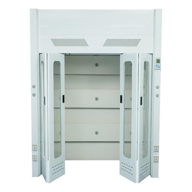
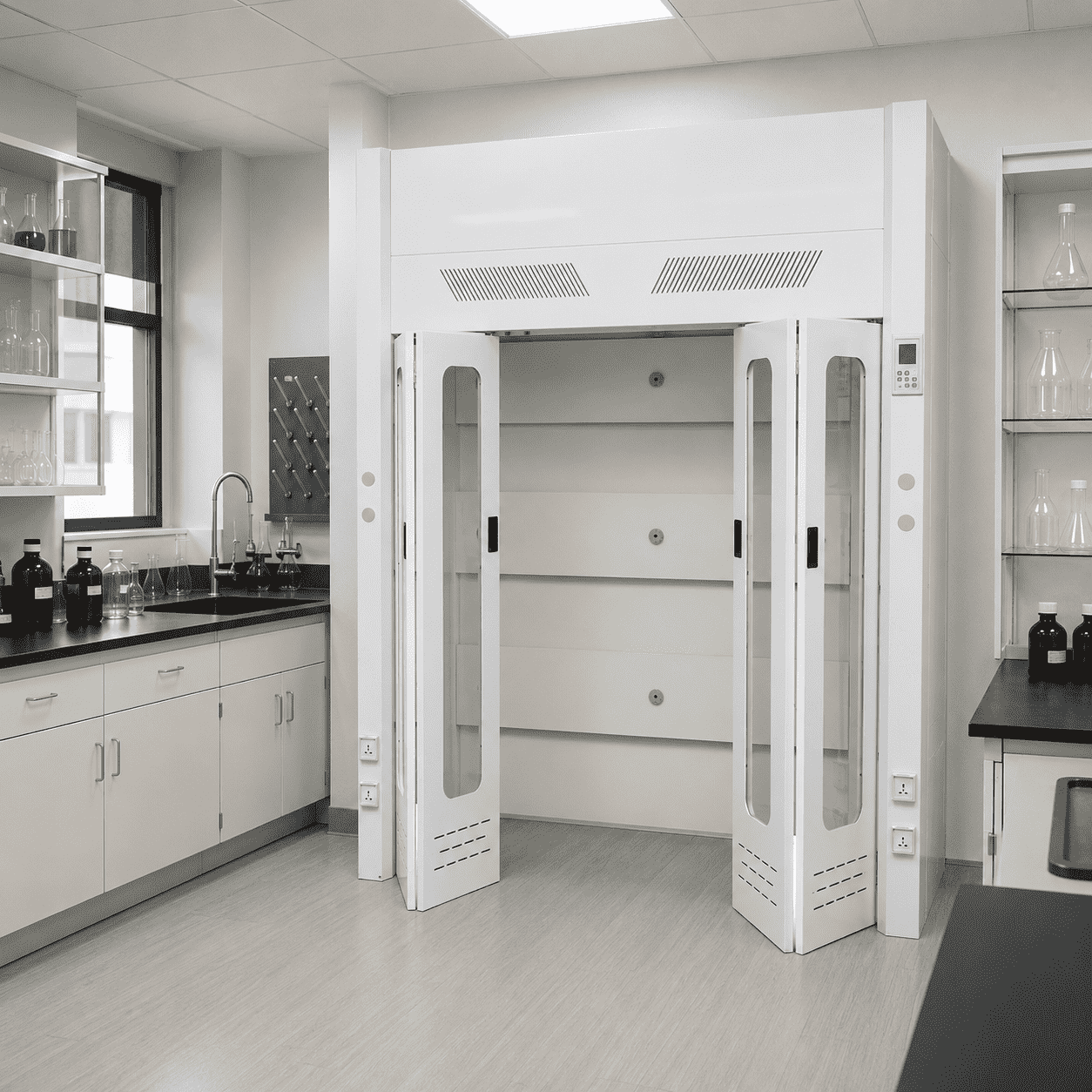
A walk-in fume hood is a floor-mounted, ducted enclosure for laboratory apparatus that is too tall, wide, heavy or difficult to load into a conventional benchtop hood. Instead of placing the process on a normal raised work surface, the enclosure provides a full-height chamber with a floor-level or low-threshold access path. This arrangement allows reactors, equipment racks, mobile frames and assembled pilot apparatus to be positioned before the sash or door is set to its defined operating condition.
What This Walk-In Fume Hood Is
The walk-in fume hood is selected around the complete apparatus and workflow rather than the nominal cabinet width alone. Equipment dimensions establish the first boundary, but the usable chamber must also leave room for valves, hoses, cables, moving parts, loading movement, service access and airflow around the apparatus. A 2000 mm reference chamber height, for example, is not automatically a 2000 mm usable equipment height once the baffle, exhaust path, utility connections and operating clearance are considered.
Floor-mounted fume hoods can be configured with horizontal sliding panels, multi-panel vertical sashes, folding access or a combined arrangement. The opening strategy affects how equipment enters the chamber, how an operator reaches the process from outside the enclosure and how much open area the exhaust system must support. For that reason, the sash arrangement, normal operating opening and setup opening are selected together with the chamber and exhaust design.
Floor-Level Chamber, Personnel And Exhaust-System Boundary
The term walk-in is a market name for the walk-in fume hood form. It does not describe an occupied work booth and does not permit a person to enter while hazardous material is being generated or while a hazardous concentration may remain. Any entry needed for equipment setup, cleaning or maintenance requires a project procedure for process shutdown, isolation, ventilation and verification before access.
The hood is also one part of a laboratory exhaust system. Its chamber, sash, baffle and exhaust connection establish the local enclosure, while the remote fan, duct route, discharge, make-up air, treatment equipment and room controls determine how that enclosure operates in the building. These items are coordinated as one system, but they are included in the delivered scope only when the quotation lists them. The final configuration therefore follows the apparatus drawing, process hazards, room layout and agreed acceptance plan rather than the walk-in fume hood name alone.
Product Selection Summary
Select a floor-mounted fume hood when the apparatus cannot be safely loaded, operated or serviced on a standard laboratory worktop. The early decision is governed by the apparatus envelope, access movement, process hazards, required operating opening and building exhaust conditions. Nominal cabinet width is only one part of that decision.
When to Choose a Walk-In Fume Hood
The walk-in fume hood family is a practical starting point for tall reactors, mobile equipment frames, pilot assemblies, drum-scale handling and equipment racks that need a floor-level loading path. It is also useful when utilities, valves or moving components extend beyond the footprint of the main apparatus and would be obstructed by a raised work surface. The selected chamber must accommodate the equipment during loading, normal operation, sampling, adjustment and maintenance, not only when the apparatus is stationary.
The process must be suitable for a ducted chemical fume hood, and the laboratory must be able to provide the required exhaust, make-up air, electrical supply, utilities and discharge arrangement. A wide access opening can simplify setup, but normal operation should use the smallest practical opening that still supports the task and the agreed containment strategy.
| Decision Area | Information To Provide | What It Determines |
|---|---|---|
| Apparatus envelope | Maximum width, depth, height, weight, attachments and operating movement | Chamber size, clear opening, floor support and internal clearance |
| Process condition | Chemicals, quantities, concentration, temperature, duration and frequency | Hood family, exposed materials, spill strategy and exhaust-treatment review |
| Access sequence | Loading direction, cart or rigging method, setup opening and operator reach | Sash or door arrangement, threshold and room clearance |
| Operating opening | Normal opening, maximum simultaneous opening and emergency condition | Design airflow, control sequence and room make-up air |
| Building interfaces | Available static pressure, duct route, fan location, utilities and controls | Exhaust collar, system scope, connection points and commissioning plan |
| Delivery route | Doors, corridors, elevators, ceiling clearance, turning space and final access | Complete or sectional delivery, assembly method and installation sequence |
Select A Different Hood When
A benchtop fume hood is usually more efficient when the apparatus fits comfortably above a normal work surface and does not require floor-level loading. A distillation hood may be more appropriate when additional vertical clearance is needed but the process still benefits from a raised work surface. Two-sided teaching work, high-temperature acid digestion, perchloric-acid work, radiochemical use and defined hazardous-area applications require their own product and system review.
Do not use a floor-mounted fume hood as a substitute for an occupied process enclosure, a room-scale ventilated booth, a biological safety cabinet or a complete pilot-plant room. Large dimensions do not establish suitability for high toxicity, explosive atmospheres, energetic reactions or unrestricted heat release. Those conditions require project-specific hazard analysis and supporting system design.
Information Needed Before Selection
Begin with a dimensioned apparatus drawing and mark every hose, cable, exhaust branch, access panel, moving arm and maintenance zone. Add the process description, chemical inventory, maximum temperature, heat output, spill scenario and operating sequence. The room package should show the hood location, floor construction, delivery route, ceiling services, available exhaust pressure, make-up air and nearby doors or supply diffusers.
This information allows the proposed configuration to state the chamber and opening arrangement, exposed materials, exhaust and control scope, utility positions, delivery method and unresolved project items. Without it, a quotation can describe only a product family, not a project-ready floor-mounted enclosure.
Key Specifications And Reference Sizes
The specification schedule should make the hood comparable without presenting planning values as unconditional performance. For a walk-in fume hood, the most important distinction is between the outside cabinet, the nominal chamber, the clear access opening and the usable apparatus envelope. These dimensions become progressively smaller as sash tracks, baffles, services, thresholds and operating clearances are added.
Core Configuration And Order Boundary
The base product is a configurable floor-mounted hood enclosure with a front access system, internal liner and baffle arrangement, lighting provision, service-access zones and one or more exhaust connections. The final schedule identifies the exterior construction, liner, floor pan, sash or door system, service fixtures, electrical package, airflow monitoring and control interfaces that apply to each hood tag.
Equipment installed inside the chamber is not part of the hood unless it is listed in the quotation. The same rule applies to the remote exhaust fan, building ductwork, roof discharge, make-up air system, room controller and downstream exhaust treatment. These elements must be coordinated with the hood, but coordination does not make them part of the supplied package automatically.
Reference Size, Chamber And Exhaust Table
The following metric families provide an early planning basis. They help compare the relationship between cabinet width, nominal chamber width and exhaust demand. Final dimensions and airflow are confirmed from the apparatus, selected opening arrangement, process and site exhaust design.
| Reference Width | Reference Overall Size W x D x H | Reference Chamber Size W x D x H | Reference Exhaust Volume |
|---|---|---|---|
| 1200 mm | 1200 x 850 x 2350 mm | 960 x 680 x 2000 mm | 700-1300 m3/h |
| 1500 mm | 1500 x 850 x 2350 mm | 1260 x 680 x 2000 mm | 900-1700 m3/h |
| 1800 mm | 1800 x 850 x 2350 mm | 1560 x 680 x 2000 mm | 1300-2100 m3/h |
Projects working in imperial dimensions may also evaluate 48, 60, 72, 84 and 96 inch width families. Those widths indicate common market planning increments, not a promise that every depth, opening, material and exhaust package is available as a stock combination.
Clear Opening And Usable Equipment Envelope
The nominal chamber dimensions describe the internal enclosure before all project constraints are applied. The clear loading opening is measured between the parts that actually limit equipment entry, including posts, sash frames, tracks, handles, threshold and any temporary lifting or restraint hardware. If the apparatus is loaded on a cart or skid, the wheel path, turning radius, handle height and method used to cross the threshold also need to fit.
The usable equipment envelope must leave clearance behind and around the apparatus for air to reach the baffle and exhaust path. It must also reserve space for hoses, electrical cables, drain lines, utility valves, sampling access and components that move during operation. Heat-producing equipment may require additional separation from the liner, glazing and services. These constraints are plotted on the apparatus drawing before the final chamber and access opening are released.
Normal operation and setup may use different opening conditions. A large setup opening may be required to load the equipment, while a smaller defined opening is used when the process is active. The schedule should identify both conditions and state whether the access system includes stops, position indication, interlocks or a control sequence. Exhaust volume cannot be selected from the maximum cabinet width while ignoring the actual open area.
How To Use The Reference Values
The published exhaust ranges are planning values associated with the three reference families. They do not replace the installed design calculation. Final airflow depends on the active opening, selected sash system, apparatus obstruction, baffle arrangement, duct pressure, room air movement and agreed containment objective. A final equipment schedule should therefore pair the selected size with a normal operating opening, setup opening, design airflow, available static pressure, exhaust-connection data and acceptance method.
Dimensions require the same discipline. Confirm whether each value is an exterior cabinet dimension, nominal chamber dimension, clear opening or usable equipment envelope. State tolerances and connection projections where they affect the room layout. Also identify the required ceiling zone for exhaust connections, lighting access and sectional assembly. A hood that fits between two walls can still be unserviceable if the upper connections or sash mechanism cannot be reached.
The final quotation should return a tag-specific schedule rather than only repeating the reference table. That schedule identifies the approved dimensions, opening arrangement, material configuration, exhaust and control interfaces, included services, delivery format and unresolved project inputs. Those fields define the delivered product.
Construction, Floor Interface And Equipment Access
The enclosure must be configured as a continuous path from the room floor to the exhaust connection. Exterior panels, liner, baffle, floor pan, sash, seals and services do not experience the same exposure, so they should not be reduced to one general material label. Each component is selected from the actual chemistry, temperature, impact, cleaning and maintenance conditions at its location.
Exterior, Liner, Baffle And Floor-Pan Selection
The exterior supports the enclosure, sash system and service zones while providing access for installation and maintenance. Its finish is selected for the laboratory environment and expected cleaning practice. The liner and baffle face the process directly and require separate review against vapors, droplets, condensate, heat and mechanical contact. A liner that is suitable for one chemical at room temperature may not remain suitable when concentration, temperature or exposure duration changes.
The baffle must remain accessible and maintain a clear path to the exhaust connection. Tall racks, vessels and temporary shielding should not be placed against it or used to support hoses and cables. Where the process can release liquid, the floor interface may use a project-specific pan, curb, threshold or drain arrangement. The design must state how a spill is retained, inspected and removed, and whether a drain is prohibited, capped or connected to an approved waste system.
Sash And Door Arrangement By Access Requirement
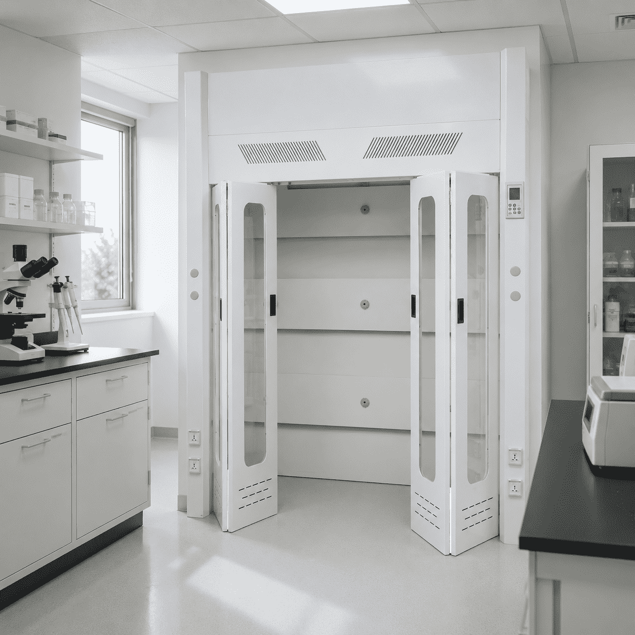
Horizontal sliding panels reduce the simultaneous open area while preserving access to selected parts of a wide process. Multi-panel vertical sashes can provide a tall opening for setup, but their operating height and counterbalance system must suit the enclosure width and ceiling zone. Folding or bifold access may help clear the loading path where the room has enough swing and standing space. A combined arrangement can separate equipment setup from routine hand access.
Selection should begin with a movement study. Mark the largest equipment cross-section, lifting points, cart frame, hose bundles and any component that protrudes during loading. Then mark the normal operator reach and sightline. The chosen opening must let the apparatus enter without removing safety-critical parts while allowing the process to run with a smaller, controlled opening whenever practical. Stops, latches, position indication and interlocks are specified from that operating sequence.
Threshold, Services And Apparatus Obstruction
A flush or low-threshold arrangement simplifies roll-in access, but it must still provide the required structural edge, seal and spill strategy. Raised thresholds improve containment in some configurations but can interfere with casters, carts or lifting equipment. The project drawing should show the finished floor elevation, any floor joint, anchor zones, leveling method and the exact transition the apparatus must cross.
Water, gas, vacuum, electrical and data services are located from the process layout rather than copied from a standard benchtop hood. Controls and isolation points should remain reachable from outside the enclosure. Internal hoses and cables need supported routes that do not cross the sash path, create a trip point, rest on hot equipment or block baffle openings. Electrical components exposed to the chamber or a defined hazardous location require a separate project review; an optional light or outlet does not establish whole-hood suitability.
Maintenance And Future Equipment-Removal Clearance
Routine maintenance requires access to sash tracks, counterbalances, service panels, light fittings, baffles, exhaust connections and monitoring devices. The room layout should preserve that access after neighboring benches, pipes and ceiling services are installed. Removable panels are useful only when they can actually be removed without dismantling the apparatus or adjacent furniture.
The same planning applies to the equipment. A vessel may enter before utilities and ductwork are completed but become impossible to remove after commissioning. Verify the future route for the largest replaceable component, including the direction of travel, lifting clearance and temporary sash or panel removal. Where the hood is supplied in sections, identify the joints that may be reopened, the seals that must be replaced and the inspections required after reassembly.
Construction decisions should finish with a component schedule. For each exposed part, record the selected material or finish, exposure basis, cleaning method and replacement access. For each opening and panel, record its operating purpose. This converts a general floor-mounted cabinet into a maintainable enclosure configured around the actual process.
Airflow, Exhaust And Control Integration
A floor-mounted hood is not sized by chamber volume alone. Containment depends on how room air enters the active opening, moves around the apparatus, reaches the baffle and leaves through the exhaust connection under the installed pressure condition. Large equipment can change every part of that path, so the airflow design must use the final apparatus layout and sash sequence.
Air Path Around Tall Apparatus
The apparatus should be placed with enough rear, side and upper clearance for air to move past it without creating isolated pockets. Broad panels, closely spaced racks and large vessels can divide the chamber into separate flow zones. Hot equipment adds buoyant plumes that may rise toward the sash header or lighting zone instead of following the intended path. Hoses, temporary screens and stored containers can create additional obstructions after commissioning.
Review the arrangement in plan, front and side views. Mark vapor-release points, heat sources, moving parts and the baffle openings that must remain clear. Where multiple exhaust connections or baffle zones are used, their purpose should be stated in the project schedule. The final arrangement should also preserve access for inspection and cleaning so a blockage can be found and corrected rather than becoming a permanent operating condition.
Active Opening, Face Velocity And Design Airflow
The active opening is the total unobstructed area through which room air enters during a defined operating condition. A wide hood with several sliding panels may use only one local opening during routine work, while equipment loading may require a much larger temporary opening. A vertical or combined sash can create another set of conditions. Each relevant state should be listed separately: closed or standby, normal operation, setup/loading and any defined emergency mode.
Face velocity is meaningful only when it is tied to the measured opening and test method. Multiplying a target velocity by a nominal opening can provide an early airflow estimate, but it does not prove containment and does not account for leakage paths, baffle behavior, equipment obstruction, room cross drafts or control response. The design airflow is finalized with the hood configuration, duct system and installed acceptance criteria.
The reference exhaust ranges in the specification table are therefore comparison values, not a command to set every hood at the upper or lower end. The project schedule should state the normal operating opening and airflow, any setup opening and airflow, the control tolerance or response requirement where applicable, and the method used to verify performance after installation.
Exhaust Collar, Static Pressure, Fan And Duct Boundary
One or more exhaust collars may be required according to hood width, airflow distribution and duct layout. Collar diameter and location are selected with the internal baffle and available ceiling zone. The connection must allow the duct to be installed and serviced without loading the hood structure or blocking sash and lighting access.
Available static pressure is checked at the hood connection under the defined airflow condition. The fan must overcome losses through the hood, collar, duct fittings, dampers, treatment equipment and discharge while maintaining the required operating point. A fan selected only from free-air volume can fail once the full system resistance is added. Duct velocity, material, drainage, cleanout, discharge location and any exhaust treatment are separate design fields that follow the process hazard and local requirements.
The quotation should identify whether the hood supplies only an exhaust collar, a control damper or valve, an airflow monitor, a fan package, ductwork or treatment equipment. When these items are by others, the schedule should still state the required interface so the building designer can complete the system without guessing.
CAV, VAV, Monitoring And Room-Air Coordination
A constant-air-volume arrangement maintains a defined exhaust condition while the sash opening changes within its permitted range. A variable-air-volume arrangement adjusts airflow in response to a measured or commanded condition and can reduce exhaust when the active opening is smaller. Either approach requires a clear sequence, suitable sensing, an actuator or airflow-control device, alarm behavior and installed commissioning. Sash or actuator position by itself is not proof of actual airflow.
An airflow monitor should indicate the condition that matters to the agreed operating method and provide an understandable response when that condition is outside range. The project defines alarm limits, delay, mute or reset behavior, interlocks and the action expected from the operator. If a large setup opening cannot maintain the normal operating condition, the control sequence should identify that state rather than presenting it as routine containment.
The room must replace the air removed by the hood without directing a strong supply jet or door-induced cross draft across the opening. A wide floor-mounted hood can influence room pressure and nearby exhaust devices, especially when several panels are open. Coordination therefore includes make-up air quantity and distribution, room pressure intent, door operation, nearby diffusers and the simultaneous operating state of other hoods.
Commissioning brings these elements together. The hood is checked with its actual sash arrangement, installed duct system, controls and representative apparatus configuration. The agreed plan may include airflow measurements, monitor and alarm checks, sash/interlock operation and additional containment testing where required. Final acceptance applies to the installed system and documented condition, not to the cabinet in isolation.
Applications, Configuration And Product Selection
The strongest reason to select the walk-in fume hood family is physical fit: the process needs a ducted enclosure, but its apparatus cannot be loaded, operated or serviced effectively on a conventional laboratory worktop. The final decision still depends on the process hazard. A large chamber solves an equipment-envelope problem; it does not automatically solve material compatibility, temperature, fire, explosion, radiological or exhaust-treatment requirements.
Suitable Large-Equipment Laboratory Work
Common candidates include tall reaction assemblies, equipment racks, pilot-scale process frames, mobile test equipment, drums or containers that must remain near floor level, and apparatus with pumps, piping or controls that extend beyond a normal benchtop chamber. The hood can also support temporary loading of a large assembly when the operating process uses a smaller defined opening after setup.
Each application is reviewed from the release point outward. Identify where vapor, aerosol, heat or particulate may be generated; how the operator charges, samples, adjusts and cleans the process; and which components move or require access. The enclosure should keep the release inside the intended capture zone while allowing the operator to remain outside the chamber during hazardous operation.
A floor-mounted format may also help when the apparatus is assembled on a skid or cart. In that case, verify the loaded wheel or support reactions, threshold crossing, restraint method and final anchoring. Mobile equipment should not be assumed to remain in a repeatable airflow position unless the design includes stops, alignment references or another controlled placement method.
Conditions Requiring A Special-Purpose Hood
High-temperature corrosive digestion should be evaluated as an acid digestion fume hood project because liner, baffle, work surface, glazing and exhaust treatment may all require a different basis. Perchloric-acid work requires a dedicated perchloric acid fume hood and compatible wash-down exhaust path rather than a general floor-mounted enclosure.
Defined hazardous areas or flammable-vapor electrical requirements belong to an explosion-proof fume hood review. Radiochemical work requires contamination-control, decontamination, work-surface loading and shielding-interface decisions associated with a radioisotope fume hood. Tall apparatus that can remain on a raised surface may be better served by a distillation fume hood.
The process assessment should also identify energetic reactions, pressure release, very high toxicity, substantial heat, heavy particulate, biological hazards and any requirement for an occupied ventilated enclosure. These conditions are not approved by choosing a larger cabinet or a corrosion-resistant liner.
Configuration And Customization Sequence
Configuration should move from the least flexible constraint to the most adjustable. Start with the process and maximum apparatus envelope. Confirm the room location and physical route. Set the chamber, clear opening, threshold and sash arrangement. Select exposed materials and service locations. Then coordinate airflow, exhaust connections, controls, room air and supplied scope. This order prevents a door style or cabinet width from being chosen before the equipment and exhaust conditions are understood.
| Configuration Stage | Required Project Evidence | Output For The Hood Schedule | Hold Point |
|---|---|---|---|
| Process and hazard | Chemicals, quantities, temperature, duration, release and cleaning method | Correct hood family, exposed-component basis and treatment review | Special hazard remains unresolved |
| Apparatus and workflow | Dimensioned equipment drawing, movement, utilities, heat and service zones | Chamber, usable envelope, opening and access arrangement | Largest operating condition is unknown |
| Room and route | Plan, elevations, door/elevator data, floor and ceiling services | Delivery sections, installation method, floor interface and maintenance clearance | Delivery or future removal route does not close |
| Exhaust and controls | Opening states, available pressure, duct route, fan, make-up air and BMS sequence | Airflow basis, collar arrangement, CAV/VAV package, alarms and interfaces | Installed operating point cannot be supported |
| Commercial scope | Quantity, hood tags, destination, required documents and responsibility matrix | Included equipment, exclusions, unresolved items, delivery and pricing | System responsibilities remain ambiguous |
Information Required For A Project-Ready Quotation
For each hood tag, provide the application, chemical and physical hazards, maximum apparatus dimensions and weight, operating heat load, required chamber and opening, normal/setup/emergency opening states, and the proposed loading and maintenance route. Include the room plan and elevations, finished floor information, anchoring constraints, ceiling clearance and nearby supply diffusers or doors.
The exhaust package should state the design airflow basis, available static pressure, collar or duct constraints, fan location, discharge requirement, make-up air strategy and any scrubber or other treatment. Control inputs should include power, CAV/VAV intent, sash-position or airflow sensing, alarm and interlock sequence, BMS protocol and defined fail condition. List every required water, gas, vacuum, drain, electrical and data service with its preferred location.
Commercial information includes quantity, destination, required delivery date, complete or sectional shipment, installation responsibility, acceptance documentation and any requested spare or replacement parts. The returned quotation should identify the proposed configuration, reference and project-confirmed values, supplied scope, exclusions, unresolved technical items and pricing. Approved drawings and the final tag schedule, rather than the family description alone, define the delivered hood.
Installation, Commissioning And Lifecycle Access
Installation begins before the hood is manufactured. A floor-mounted enclosure, its largest delivery section and the apparatus it will contain must all reach the final room, fit the prepared floor and connect to the exhaust and services without blocking future maintenance. The approved installation package should therefore combine route drawings, floor details, assembly information, system interfaces and acceptance responsibilities.
Delivery Route And Sectional Installation
Survey the route from unloading point to final position. Record clear door and elevator openings, corridor widths, turning radii, ramps, floor transitions, ceiling height, overhead services and the load limit of lifting or transport equipment. Packaging dimensions can exceed the finished hood, so the route check must use the shipping section and handling method rather than the installed cabinet alone.
Where a complete unit cannot pass, sectional delivery can divide the enclosure into planned structural and panel assemblies. The submittal should identify section sizes and weights, lifting points, joint locations, field fasteners, sealants, wiring or service connections and the sequence used to restore the chamber and exhaust path. Field-cut openings and unplanned disassembly should not replace a documented sectional design.
Floor, Threshold, Anchoring And Apparatus Loading
Confirm the finished floor elevation, level, load capacity, joints, coatings and any embedded utilities before setting the hood. Anchor locations must avoid structural conflicts and concealed services. If leveling creates a gap, the design should state how the gap is closed and cleaned. The threshold, floor pan or curb must align with the spill-control decision and the equipment loading method.
Apparatus loading should follow an approved sequence. Some equipment enters before the front access assembly is completed; other systems are rolled through the finished opening. Protect sash tracks, panels, baffles and services from rigging loads. Once positioned, secure or reference the apparatus so routine operation does not move it into the baffle path or alter the defined opening clearance. Utilities should be connected without creating unsupported hoses, trip points or hidden leak locations.
Exhaust, Control And Functional Acceptance
Before operation, inspect chamber joints, seals, panels, baffles, sash travel, stops, counterbalance, lighting, service isolation and exhaust connections. Verify duct support so its weight is not transferred to the hood. Confirm fan rotation, control-damper or valve action, monitor and alarm behavior, interlocks, BMS points and the room pressure or make-up air condition specified by the project.
Airflow checks use the agreed sash position and opening definition. The recorded condition should include the operating airflow, relevant pressure, room state and representative apparatus arrangement. Where the project requires containment testing, follow the approved method and acceptance criteria for the installed system. A running fan, a displayed actuator position or a single unreferenced velocity reading is not an acceptance result.
Any setup opening that differs from the normal operating condition should be labeled and tested according to its intended use. If it is for loading only, the operating procedure and controls should prevent it from being mistaken for the routine working position.
Inspection, Cleaning And Future Equipment Removal
The maintenance plan should define inspection intervals and access for the sash system, baffles, floor pan, seals, lighting, services, monitor, exhaust connection and controls. Cleaning methods must match the selected liner, glazing, seals and floor materials. Process residues, spill waste and removed components are handled under the laboratory’s chemical and waste procedures.
Changes to the apparatus, process chemistry, operating temperature, opening pattern, exhaust system or room air distribution can invalidate the original operating basis. Review those changes before use and repeat the relevant verification. Replacing a large vessel or rack may require temporary removal of panels or sash components; the approved removal route and reassembly checks should already be available.
Personnel access for cleaning or maintenance is permitted only after the process is shut down, energy and services are isolated as required, the enclosure is ventilated, and the laboratory’s clearance procedure confirms that entry is acceptable. The walk-in fume hood name never replaces that procedure.
Related Laboratory Fume Hoods
Choose the enclosure from the equipment geometry and process hazard rather than size alone. A benchtop fume hood suits apparatus that fits above a normal work surface. A distillation fume hood provides extra vertical clearance while retaining a raised equipment surface. Dedicated perchloric acid, acid digestion, radioisotope and explosion-proof fume hoods address hazards that a general large chamber does not establish. Review the complete laboratory fume hood range when more than one constraint applies.
Frequently Asked Questions
Can a person work inside a walk-in fume hood?
No. Walk-in is the market name for a floor-mounted product form, not permission to occupy the chamber during hazardous operation. Any access required for setup, cleaning or maintenance must follow the laboratory’s shutdown, isolation, ventilation and clearance procedure before a person enters the enclosure.
What equipment information is needed to size the chamber?
Provide a dimensioned drawing showing the maximum equipment envelope, weight, attachments, moving parts, utility connections, heat output, operating access and maintenance zones. Include the cart, skid or rigging method used for loading. The chamber must fit the complete workflow, not only the main equipment body.
What is the difference between chamber size and usable equipment envelope?
Chamber size is the nominal internal enclosure dimension. The usable equipment envelope is smaller because it reserves space for the sash, baffle, exhaust path, services, hoses, movement, operator reach and maintenance. Final fit is checked against the usable envelope and clear loading opening.
What reference sizes are available?
The current planning families use 1200, 1500 and 1800 mm overall widths with an 850 mm reference depth and 2350 mm reference height. Corresponding nominal chamber sizes and exhaust ranges are listed in the specification table. Final dimensions are confirmed for the apparatus, opening and site.
How is the required exhaust volume selected?
It is selected from the defined active opening, sash arrangement, apparatus obstruction, baffle configuration, available static pressure, room air movement and acceptance basis. The published ranges support preliminary comparison but do not replace the project calculation and installed verification.
Which sash or door arrangement should be selected?
Use the arrangement that admits the equipment while allowing a smaller controlled opening for routine work. Horizontal sliding panels suit selective access across a wide face. Vertical, folding or combined systems may provide greater setup clearance. Room space, operator reach, opening area and maintenance access must all be checked.
Can the hood be delivered and assembled in sections?
Yes, sectional delivery can be configured when doors, corridors, elevators or turning space prevent complete-unit delivery. The approved package must define section dimensions, joints, lifting points, field connections, seals and post-assembly inspections. Sectional construction should be planned before manufacture rather than improvised on site.
Are the fan, ductwork and treatment system included?
Only when the quotation lists them. The hood must be coordinated with the remote fan, duct, discharge, make-up air, controls and any exhaust treatment, but these items may be supplied by different parties. The final responsibility matrix should identify every interface and included component.
When is a distillation or special-purpose hood a better choice?
Choose a distillation hood when tall apparatus can remain on a raised surface and does not need floor-level loading. Select a dedicated hood when perchloric acid, hot corrosive digestion, radiochemical contamination control or a defined hazardous area governs the design. Those requirements cannot be added by product name alone.
Contact The Xicheng Engineering Team Today
Send the apparatus drawing, maximum equipment envelope, process chemicals and temperatures, required access opening, room layout, delivery route, exhaust basis, available static pressure, utility schedule and control sequence. Xicheng will use these inputs to prepare a project-specific chamber, opening, material, exhaust-interface and delivery proposal with the applicable commercial quotation.
Shenzhen Office: No. 34 Zhenxing Road (Shengtaian Heavy Industrial Park B), Loucun, Guangming New Dist, Shenzhen, Guangdong, China
WhatsApp: +86 181 2647 8161
Engineering Mailbox: fanalax34@gmail.com