


Description
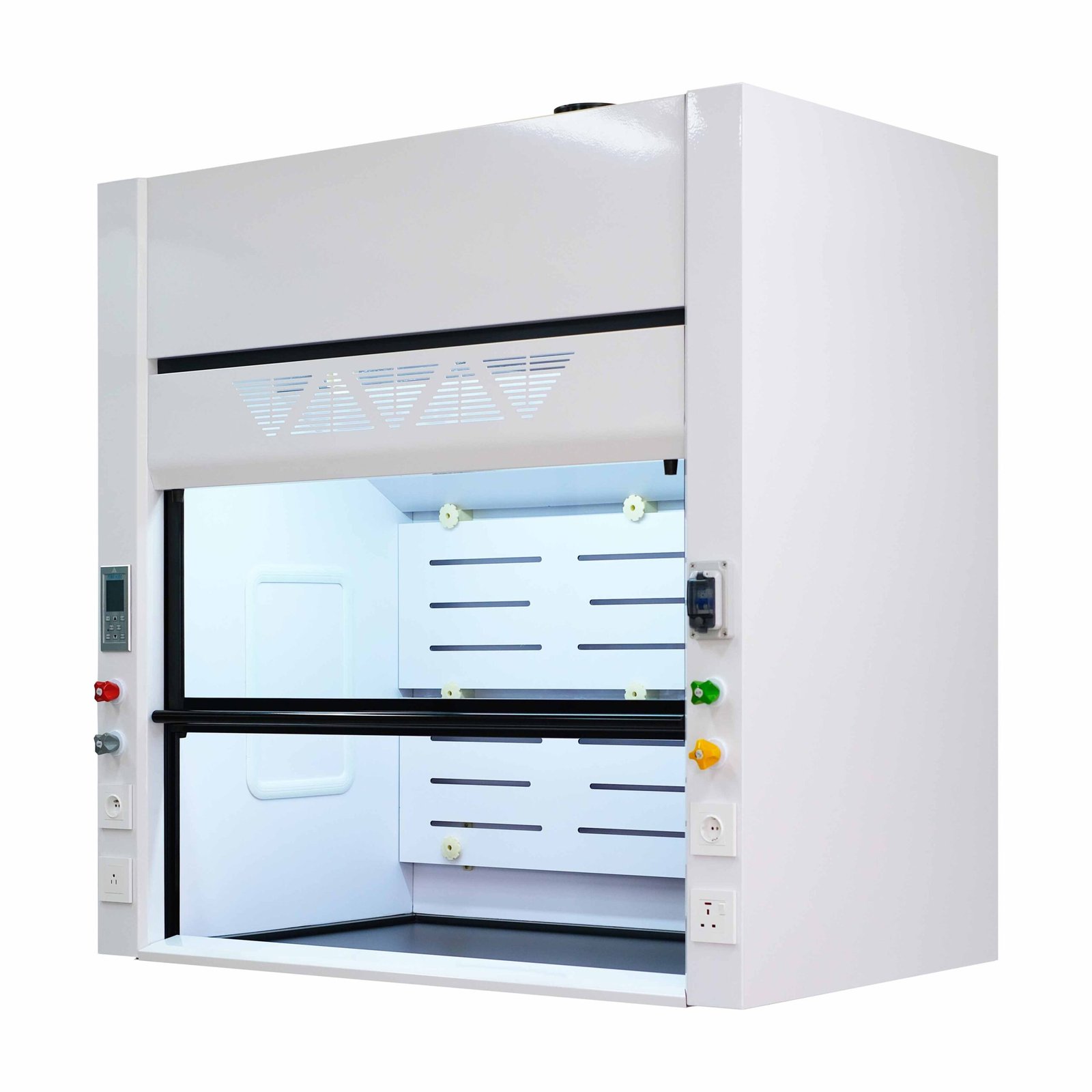
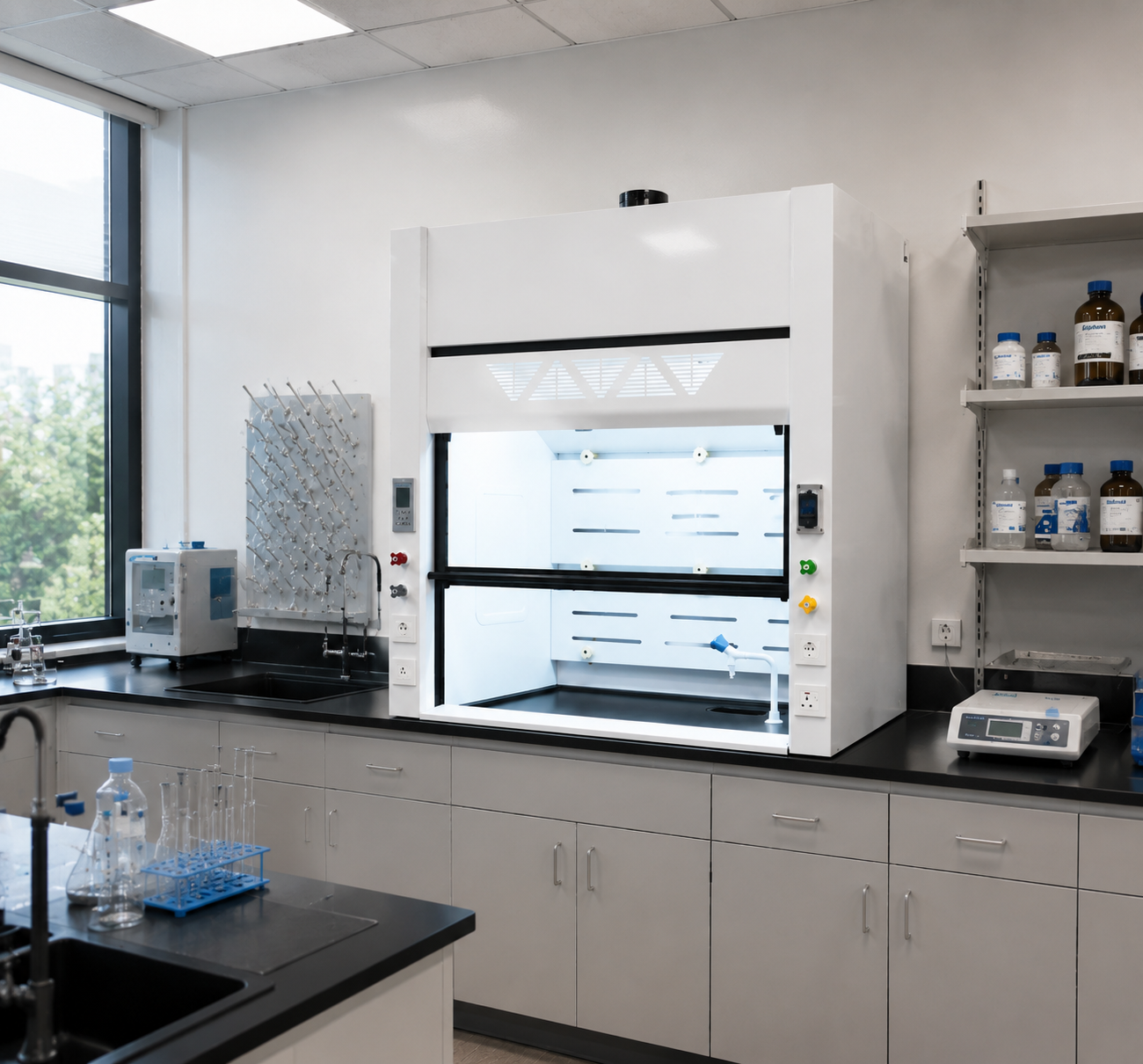
A benchtop fume hood places the ventilated work chamber above an existing laboratory worktop or a separately specified support. Room air enters through the sash opening, passes across the process zone and leaves through the hood’s exhaust connection. A connected laboratory exhaust system then carries the contaminated air to the approved discharge or treatment point.
Product Overview
What This Benchtop Fume Hood Is
This ducted hood superstructure combines an outer enclosure, internal liner, rear baffle, vertical sash, air-entry components and a top exhaust connection. Its installation form is useful where the laboratory already has suitable casework or where the hood must be coordinated with a project-specific bench. Reference widths from 900 to 1800 mm allow the chamber to be matched to compact analytical work, routine chemical handling or wider apparatus arrangements.
The term benchtop identifies how the enclosure is supported. It does not mean that the hood is portable, recirculating or supplied with an integral base. The selected worktop and supporting structure must carry the hood, resist the expected exposure and maintain a stable, sealed interface throughout operation.
Superstructure, Worktop And Exhaust-System Boundary
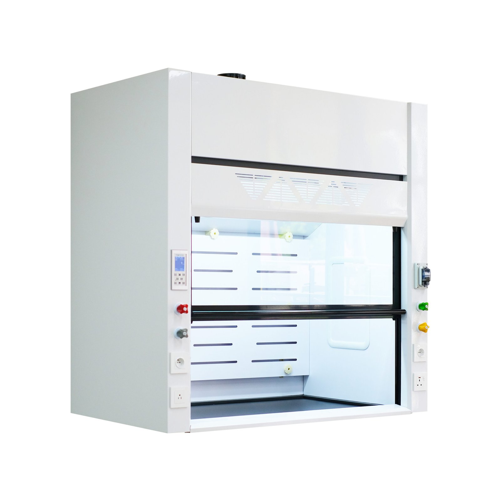
The hood body provides the chamber geometry and directs extract air toward the exhaust collar. The worktop, support, fixing method and perimeter seal determine whether that body remains level and mechanically stable. The ductwork, fan, make-up air and control system determine whether the required airflow can be maintained at the installed sash opening. These responsibilities must be coordinated rather than inferred from the cabinet width.
XICHENG can configure the hood as a superstructure-only supply, coordinate it with a matching worktop and base, or include additional exhaust and control components in the project scope. The quotation identifies the included cabinet, furniture, services, monitor, controls, fan, ductwork and treatment equipment. Anything outside that schedule remains part of the laboratory or building works.
Product Selection Summary
A benchtop chemical fume hood is a practical choice when the laboratory needs ducted containment above an existing furniture line and the process fits a conventional elevated chamber. The decision depends on more than available bench length. The support, apparatus envelope, chemical exposure and exhaust conditions must work as one installation.
When to Choose a Benchtop Fume Hood
- The work releases vapors, gases, odors or light airborne contamination that must be captured and discharged through a laboratory exhaust system.
- The apparatus can be loaded through a front sash and operated on an elevated work surface without requiring floor-level access.
- An existing bench, matching base or dedicated support can provide the required width, depth, level, load capacity and fixing points.
- The exterior, liner, baffle, work surface, sash and service components can be selected against the actual chemicals, temperature and cleaning method.
- The building can provide a suitable duct route, exhaust capacity, available static pressure, make-up air and discharge or treatment arrangement.
- The installed hood can be commissioned at the intended sash opening and operating condition.
Select A Different Hood When
Choose a floor-mounted or walk-in fume hood when tall or heavy equipment must enter at floor level, when apparatus loading cannot be handled safely over a bench, or when the process requires substantially more internal height. A distillation or high-clearance hood may be more appropriate for tall assemblies even when the equipment still rests on an elevated surface.
Special chemistry can also change the benchtop fume hood family. Perchloric-acid work may require a dedicated wash-down hood and exhaust path. Heated acid digestion, hydrofluoric-acid exposure, radiochemical work and hazardous-location electrical requirements each require a separate review of materials, drainage, decontamination, electrical construction and system boundaries. A ductless fume hood is considered only when a documented filtration strategy is suitable for the chemical list and loading; it is not a portable version of this ducted hood.
Information Needed Before Selection
Begin with the process chemical list, concentrations, operating temperatures, apparatus width/depth/height and preferred sash opening. Add the proposed hood location, available bench dimensions, worktop material, support construction and any known load or anchoring limitations. The initial exhaust review needs the intended duct route, available static pressure, room make-up-air arrangement and any treatment requirement.
This first package is enough to establish whether the benchtop format belongs in the project and which width and chamber envelope should be evaluated. Utility locations, control points, finishes, shipping breakdown and final connection details are completed during configuration and quotation.
Key Specifications And Reference Sizes
The fields below support the first comparison between a benchtop fume hood and the available furniture and exhaust conditions. They define what must be scheduled; they do not replace the approved project drawing or the airflow calculation for the installed room.
Core Configuration And Order Boundary
| Comparison Field | Available Or Reference Configuration | Confirm Before Order |
|---|---|---|
| Product form | Ducted benchtop hood superstructure | Hood-only, coordinated furniture package or wider ventilation scope |
| Mounting | Existing worktop, matching base or dedicated support | Bench width, depth, level, load capacity, fixing and perimeter seal |
| Reference widths | 900 / 1200 / 1500 / 1800 mm | Usable chamber width, apparatus clearance and site access |
| Exterior construction | Project-selected cabinet material and finish | Room exposure, cleaning method and service-zone requirements |
| Chamber components | Selected liner, baffle and work-surface materials | Chemicals, concentration, temperature, spills and direct contact |
| Sash | Vertical viewing sash with project-specific opening | Maximum opening, working opening, apparatus loading and control sequence |
| Exhaust interface | Top or project-specific exhaust connection | Collar size and position, airflow, static pressure, duct route and fan duty |
| Services | Lighting, outlets and service fixtures as selected | Voltage, outlet standard, water/gas/vacuum type and connection side |
| Airflow control | Monitor, alarm, CAV, two-state or VAV options | Required signals, interlocks, BMS points and room-pressure sequence |
| Excluded unless listed | Worktop, base, fan, ductwork and treatment equipment | Exact supply schedule and responsibility for every external interface |
Reference Width And Planning-Envelope Table
Two documented configuration families are shown because both are useful during layout planning. Configuration A provides 1200, 1500 and 1800 mm models with a deeper enclosure. Configuration B adds a 900 mm option and uses a shallower 750 mm external depth. Values from one family must not be combined with the chamber or exhaust values of the other.
| Planning Family | Width | Reference Overall W x D x H | Reference Chamber W x D x H | Reference Exhaust Volume |
|---|---|---|---|---|
| A | 1200 mm | 1200 x 850 x 1500 mm | 960 x 680 x 1150 mm | 700-1300 m3/h |
| A | 1500 mm | 1500 x 850 x 1500 mm | 1260 x 680 x 1150 mm | 900-1700 m3/h |
| A | 1800 mm | 1800 x 850 x 1500 mm | 1560 x 680 x 1150 mm | 1300-2100 m3/h |
| B | 900 mm | 900 x 750 x 1400 mm | 868 x 650 x 1200 mm | Confirm for opening and system |
| B | 1200 mm | 1200 x 750 x 1400 mm | 1168 x 650 x 1200 mm | Confirm for opening and system |
| B | 1500 mm | 1500 x 750 x 1400 mm | 1468 x 650 x 1200 mm | Confirm for opening and system |
| B | 1800 mm | 1800 x 750 x 1400 mm | 1768 x 650 x 1200 mm | Confirm for opening and system |
Reference Exhaust-Volume Fields
The Configuration A exhaust ranges are useful for early fan and duct discussions, but they are not unconditional operating values. Final exhaust volume depends on the usable sash opening, intended face-velocity criterion, chamber geometry, baffle arrangement, duct resistance, room air movement and control strategy. Available static pressure must be stated at the hood connection, not assumed from the fan nameplate.
Configuration B intentionally leaves the exhaust value open because its dimensional table does not establish the complete airflow condition. The project schedule should record both the selected width and the required operating opening before the fan or control package is sized.
How To Use The Reference Values
First, compare the overall width and depth with the existing bench and nearby walls, services and aisles. Second, compare the internal chamber with the complete apparatus envelope, including hoses, stands and the space needed to move the sash. Third, verify that the supporting worktop can accept the selected enclosure without obstructing service penetrations or maintenance panels.
The approved drawing should then state the final external and internal dimensions, worktop interface, sash travel, exhaust-collar location, utility penetrations and access clearances. The ventilation schedule separately confirms airflow, static pressure, control points and the acceptance condition. These documents, rather than a reference width alone, define the ordered benchtop fume hood.
Mounting, Construction And Material Selection
A benchtop hood has two connected structures: the ventilated superstructure and the furniture or frame that supports it. Both must remain stable, cleanable and compatible with their own exposure. Selecting the chamber liner without checking the bench, or selecting the bench without checking the hood fixing and service route, leaves an incomplete installation.
Existing Worktop And Support Compatibility
The existing bench must provide enough usable depth for the enclosure footprint and enough width to keep the hood clear of walls, tall fittings and adjacent equipment. Its frame, cabinets and worktop must carry the installed hood and any apparatus without excessive movement or loss of level. The load path should be checked through the worktop into the frame or floor rather than judged from surface thickness alone.
Fixing points prevent movement during sash operation and routine use. Their positions must avoid drawer runners, cabinet partitions, utilities and weak worktop zones. Where the hood meets the worktop, the joint should be sealed with a material appropriate for the expected spills and cleaning agents. Service holes need collars or sealed edges so liquid cannot enter the furniture construction.
If the existing bench cannot provide these conditions, a matching base or dedicated support frame is the safer project route. This can also simplify leveling, concealed service routing and maintenance access. The final drawing should identify support points, fasteners, penetrations and the party responsible for the worktop-to-hood seal.
Exterior, Liner, Baffle And Work-Surface Selection
The exterior cabinet mainly faces the room environment, routine cleaning and incidental splashes. The chamber liner and rear baffle face the extracted process atmosphere. The work surface receives direct spills, equipment loads and local heat. These components may therefore require different materials even when they form one visible enclosure.
| Component | Available Material Direction | Selection Basis |
|---|---|---|
| Exterior shell | Coated metal or another project-selected cabinet construction | Room environment, cleaning agents, impact exposure, finish and service access |
| Chamber liner | Compact laminate, polymer, FRP, stainless or another approved liner | Chemical list, concentration, vapor exposure, temperature and decontamination method |
| Rear baffle | Material coordinated with the liner and exhaust stream | Extracted chemistry, cleanability, removability, stiffness and slot geometry |
| Work surface | Laboratory-grade project-selected top | Direct spills, heat, equipment load, sink or cup-sink cut-outs and edge containment |
| Sash glazing | Safety glazing selected for the process | Visibility, impact, heat, chemical exposure and required opening arrangement |
| Service fittings | Fixture and tubing materials selected by service | Water, gas, vacuum or other media, pressure, chemical contact and shutoff location |
| Seals and fasteners | Project-selected exposed and concealed components | Spills, cleaning agents, temperature, fixing substrate and maintenance access |
A material name is not a complete chemical-resistance statement. Concentration, temperature, contact time, vapor versus liquid exposure and mixed chemicals can change the result. Compatibility should be reviewed component by component, with the work surface and liner receiving particular attention because their exposure is more direct than the outer shell.
Sash, Services And Maintenance Access
The vertical sash provides viewing and a movable barrier while defining the opening used for airflow calculations. Its maximum travel must clear the apparatus, but the operating opening should remain a deliberate project value. Handles, guides, stops and the balance mechanism need to move without interference from taps, cables or tall equipment on the bench.
Electrical outlets and service controls are normally kept outside the chamber opening, with tubing and wiring routed through accessible side or upper service zones. The exact service type, voltage, outlet standard, control location and connection side should be scheduled before fabrication. Removable access panels must remain reachable after the hood is placed against walls, adjacent furniture or ceiling enclosures.
Airflow, Exhaust And Control Integration
The hood and the building ventilation system perform different parts of the same containment task. The enclosure shapes the opening and internal airflow path. The exhaust system provides the volume and pressure needed to move contaminated air away from the operator. Neither part should be specified without the other.
Airflow Path Through The Chamber And Baffle
Room air enters through the sash opening and crosses the front boundary into the chamber. The air then moves around the apparatus toward openings in the rear baffle and into the upper exhaust plenum. From there it leaves through the exhaust collar. The airfoil, sash geometry and baffle arrangement are intended to reduce abrupt changes in direction and distribute extraction across the chamber.
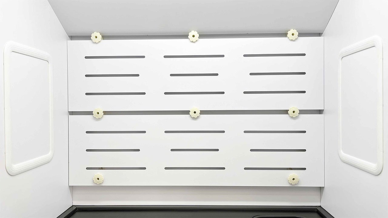
The visible two-section baffle can be removed for access to the rear chamber. Its openings should not be blocked by bottles, paper, equipment or stored materials. Apparatus should also be arranged so that it does not create a solid barrier between the sash and the baffle. If a tall device or concentrated heat source changes the normal path, its position belongs in the airflow review rather than being treated as a furniture detail.
Face Velocity, Sash Opening And Static Pressure
Face velocity describes the average air speed through a defined sash opening. Exhaust volume describes the amount of air moved in a given time. Available static pressure describes the pressure that can overcome resistance through the hood, ductwork and treatment components. These values are connected, but one cannot stand in for the others.
The operating condition must identify the hood width, working opening, target airflow criterion, exhaust volume and static pressure at the connection. Room cross-drafts, door movement, supply-air diffusers and nearby traffic can influence the opening even when the fan delivers the scheduled volume. For that reason, a reference exhaust range is an early design input, not proof of installed containment.
Exhaust Collar, Ductwork, Fan And Treatment Boundary
The top connection allows the hood to join the project exhaust duct. Its diameter, orientation and centerline must be coordinated with the available ceiling space, elbows, dampers, fire or smoke coordination where applicable, and access for inspection. Reducing or offsetting the connection can add resistance and change the fan duty.
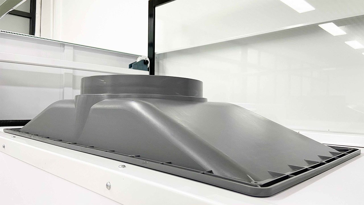
The hood connection does not automatically include the remote fan, external ductwork, stack, make-up-air system or exhaust treatment. A fan is selected from the required airflow and total system resistance, with suitable construction for the air stream. A scrubber or other treatment device is included only when the process and discharge requirements call for it. Its pressure loss, drainage, utilities and maintenance access become part of the exhaust calculation.
Room make-up air should replace extracted air without sending a disruptive jet across the hood opening. The room-pressure sequence must also account for other exhaust devices, doors and adjacent spaces. These building conditions are coordinated with the hood rather than supplied by the cabinet itself.
CAV, Two-State And VAV Options
A constant-air-volume arrangement maintains a scheduled exhaust condition independent of normal sash movement within the approved operating range. A two-state sequence changes between defined occupied and reduced modes. A variable-air-volume system adjusts airflow in response to sash position, face-velocity feedback or another approved control input. Each strategy requires compatible sensors, dampers or valves, actuators, alarms and control logic.
The selected controller should identify power, input and output signals, response requirements, alarm functions, emergency mode and BMS communication. Sash position alone does not confirm actual airflow, and a running fan does not confirm performance at the opening. Commissioning must verify the complete hood, room and exhaust sequence in the installed condition.
Applications, Fit And Product Selection
The benchtop format is most useful when the laboratory needs local ducted containment but also needs to coordinate the enclosure with existing casework, a specialist worktop or a compact room layout. The process still determines the chamber materials, opening, services and exhaust duty. Installation form alone does not determine suitability.
Suitable Benchtop Laboratory Work
Routine reagent preparation, sample treatment, small-batch wet chemistry and analytical procedures can fit the ducted benchtop hood when their vapor, heat and spill conditions are compatible with the selected chamber. The elevated work surface keeps instruments and containers at normal bench height, while the sash provides front access and a defined operating opening.
Quality-control and research laboratories may use a benchtop hood where individual stations need localized exhaust without replacing a complete furniture line. Teaching laboratories can use the format where the bench structure, services and supervision layout have been designed for the hood. Compact width options can support smaller apparatus, while wider chambers provide room for multiple items without placing them directly against the baffle.
The work description should identify the actual operation rather than only the industry. Solvent transfer, acid dilution, heated reaction, evaporation and instrument exhaust create different material and airflow demands even when they occur in the same laboratory. Quantities, concentrations, temperature and duration help distinguish a routine configuration from a special-purpose requirement.
Conditions Requiring A Different Hood
A process should move to a different product when its defining constraint cannot be resolved by changing the width or liner. Tall assemblies can require a Distillation Fume Hood with greater internal clearance. Large or floor-supported equipment can require a Walk-In Floor-Mounted Fume Hood. These options change the enclosure and installation geometry rather than merely enlarging a bench model.
Dedicated Perchloric Acid Fume Hoods and Acid Digestion Fume Hoods address specific wash-down, material, drainage or high-temperature conditions. Radioisotope work and hazardous-location requirements also require their own construction and project review. When external ductwork is not feasible, a Ductless Fume Hood can be evaluated only after the chemical list and filter-management conditions have been checked.
Configuration And Customization Sequence
- Define the process. Record chemicals, concentrations, quantities, temperatures, vapor release, heat load and any equipment that changes the airflow path.
- Check the apparatus envelope. Measure the complete width, depth and height, including stands, hoses, vessels, movements and the access needed through the sash.
- Verify the supporting furniture. Confirm worktop dimensions and material, frame construction, level, load capacity, fixing zones, service penetrations and spill-sealing method.
- Select exposed materials. Review the exterior, liner, baffle, work surface, sash, fixtures, seals and fasteners against their own chemical and thermal exposure.
- Set the chamber and opening. Choose the width and usable internal envelope, then define maximum and normal sash positions for operation and loading.
- Coordinate exhaust and room air. Establish airflow, available static pressure, duct route, fan and discharge or treatment duty, make-up air and room-pressure sequence.
- Schedule services and controls. Identify water, gas, vacuum, power, lighting, outlets, monitoring, alarms, CAV/VAV strategy and BMS points.
- Close the supply boundary. List the hood, worktop, base, fan, ductwork, controls, treatment equipment, site works, testing and documentation included by each party.
Information Required For Quotation
For a project-ready quotation, provide the chemical and process schedule; apparatus dimensions and weight; proposed hood width and working sash opening; bench plan, section and worktop details; required liner and work-surface direction; utility list and connection standards; airflow and available static pressure; duct route and discharge or treatment requirement; control sequence and BMS interface; and the required quantity and destination.
Photographs of the existing bench and ceiling route are useful for retrofit work, but they do not replace dimensions. Add room plans, furniture elevations, exhaust schematics and point lists when available. Access restrictions, door and lift sizes, installation hours and whether the bench can be modified on site should also be stated.
The quotation and approval package should identify the selected planning family, final dimensions, chamber materials, sash and service arrangement, exhaust connection, supplied controls, furniture interface and all excluded site work. This creates a checkable order for the hood and a clear handoff to the laboratory furniture, mechanical, electrical and commissioning teams.
Installation, Commissioning And Maintenance
A benchtop fume hood should be installed as a coordinated enclosure, furniture and ventilation assembly. Preparing the bench and services before delivery reduces field modification, but the installed condition still requires mechanical, electrical and airflow checks before routine use.
Bench Preparation And Pre-Installation Coordination
Confirm the delivery route, door and lift clearances, unpacking area and any need to remove sash or access panels for handling. At the final position, verify bench width and depth, worktop level, support condition, fixing zones and the location of every service penetration. The bench should be complete and stable before the superstructure is fixed.
The exhaust collar must align with the coordinated duct route without forcing the hood out of position. Allow space for the collar connection, elbows, damper or measurement points, insulation where required and future inspection. Electrical, water, gas, vacuum and drain interfaces should remain accessible and should not pass through unsealed or structurally unsuitable worktop areas.
After positioning, check that the enclosure is level, the sash travels freely and the perimeter interface is sealed as specified. Verify that adjacent cabinets, walls, taps and ceiling components do not block service panels or maintenance access. The installed furniture and fasteners should show no movement during normal sash operation.
Exhaust And Functional Acceptance
Commissioning begins with the physical configuration recorded: hood width, selected sash opening, baffle position, exhaust collar, duct arrangement, fan and control mode. Confirm fan rotation and operation, duct integrity, damper or valve position, sensor installation and room make-up-air condition before evaluating the opening.
Airflow measurements should be made using the project method and the defined sash position. The result is reviewed together with exhaust volume, available static pressure, room pressure and relevant alarm or control responses. Visual smoke work or a specified containment test may be added according to the project acceptance plan. Fan operation or sash position by itself is not sufficient evidence.
Test lighting, outlets, service fixtures, monitors, alarms, emergency functions and BMS points included in the supply. Record any final balancing or control adjustments. The acceptance file should identify the test condition and instruments so the result can be compared during future checks.
Inspection, Cleaning And Documentation
Routine inspection should keep the sash guides, air-entry path, baffle openings and exhaust connection free from obstruction. Clean the liner, work surface, sash and baffle using methods compatible with the selected materials and the process contamination. Removable baffles should be returned to their approved position after access.
Service fixtures, electrical components, seals, fasteners, controls and alarms should be checked under the laboratory’s maintenance program. Changes to apparatus, sash practice, fan speed, ductwork, room supply air or nearby partitions can alter the installed condition and should trigger a review. Keep the approved drawing, material schedule, control sequence, airflow records and maintenance actions with the equipment file.
Related Laboratory Fume Hoods
The Laboratory Fume Hoods range includes enclosure forms for different apparatus, chemistry and building constraints. A General Purpose Steel Fume Hood is the conventional choice when a coordinated full cabinet and furniture arrangement is preferred. A Walk-In Floor-Mounted Fume Hood provides floor-level clearance for large equipment, while a Distillation Fume Hood addresses tall bench-supported assemblies.
Where external ductwork cannot be provided, evaluate a Ductless Fume Hood only after confirming filter compatibility and loading. Processes involving perchloric acid, heated acid digestion, radioisotopes or hazardous-location requirements should be routed to their dedicated hood families because those conditions change more than the cabinet width or liner.
Frequently Asked Questions
Does a benchtop fume hood include the worktop and base cabinet?
Not automatically. The benchtop fume hood can be quoted as a hood superstructure only or coordinated with a worktop, base or support frame. The supply schedule should state every included furniture component, fixing item and site interface.
Can the hood be installed on an existing laboratory bench?
Yes, when the bench provides suitable width, depth, level, load capacity and fixing zones. The worktop material, support frame, service penetrations and perimeter seal must also be checked before the final drawing is approved.
What reference widths are available?
The documented planning range includes 900, 1200, 1500 and 1800 mm widths. Two reference configuration families use different depths, heights and chamber dimensions, so the selected family and final dimensions must be shown on the approval drawing.
Is a benchtop fume hood portable or ductless?
No. Benchtop describes the support and installation form. The ducted benchtop hood connects to an external exhaust system. Portable and ductless enclosures use different movement, filtration, power and chemical-compatibility criteria.
How is the required exhaust volume selected?
The exhaust calculation uses the hood geometry, defined sash opening, project airflow criterion, duct resistance, available static pressure, room air movement and control strategy. Reference volume ranges support early planning but do not replace the installed calculation and commissioning measurements.
Which liner and work-surface material should be used?
Selection depends on the chemical list, concentration, temperature, contact time, spill exposure, cleaning method and equipment load. The liner, baffle, work surface and outer cabinet are reviewed separately because they do not face the same exposure.
When should a floor-mounted or distillation hood be selected instead?
Use a floor-mounted hood when equipment must enter or operate at floor level. Use a distillation or high-clearance hood when tall bench-supported apparatus cannot fit the usable chamber and sash opening of the benchtop configuration.
Contact The Xicheng Engineering Team Today
Send the chemical and process list, apparatus dimensions, preferred sash opening, existing bench drawings, utility requirements and available exhaust conditions. XICHENG will prepare a product configuration and quotation covering the hood, furniture interface, exhaust connection, controls and confirmed supply boundary.
Shenzhen Office: No. 34 Zhenxing Road (Shengtaian Heavy Industrial Park B), Loucun, Guangming New Dist, Shenzhen, Guangdong, China
WhatsApp: +86 181 2647 8161
Engineering Mailbox: fanalax34@gmail.com