


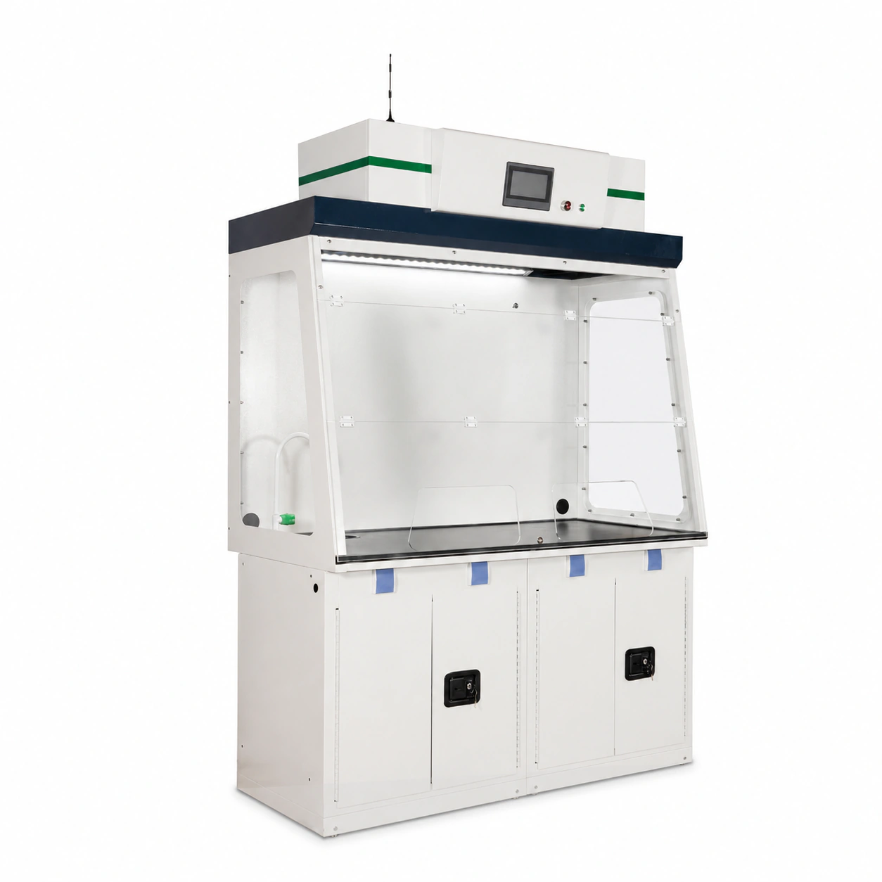
Description
Product Information:
A ductless fume hood combines a work enclosure, integral fan and selected filter package in one recirculating air path. Laboratory air enters through the defined sash opening, sweeps contaminants away from the operator’s breathing zone, passes through the configured filtration section and returns to the room. This full-size product family is intended for fixed laboratory positions where the process can be characterized well enough to select, monitor and replace the filters responsibly.
Ductless Fume Hood for Filtered Room-Air Recirculation
The main purchasing distinction is the destination of the captured air. A conventional ducted hood sends contaminated air through building ductwork to an outdoor discharge or treatment system. A filtered fume hood keeps the air path local to the cabinet, so its suitability depends on the relationship between the contaminant, filter media, cumulative loading, monitoring method and laboratory room. Eliminating an external duct connection can simplify some installations, but it transfers more of the engineering decision to process qualification and filter lifecycle management.
How the Recirculating Air Path Works
The integral fan creates inward flow at the work opening and moves chamber air toward the filter housing. The first filtration stage may remove larger particulate or protect the main media, while molecular carbon, HEPA or a combined arrangement addresses the contaminant form for which it was selected. The treated stream then leaves the upper housing and mixes with room air. The exact stage order, media grade, filter mass, fan duty and monitoring package are configuration fields; they are not established by the word ductless alone.
This air path makes the laboratory room part of the operating boundary. The room must have suitable background ventilation, adequate space around the return outlet and a procedure for responding to odor, alarm or suspected breakthrough. Equipment placed above the hood, ceiling obstructions or a poorly located supply diffuser can interfere with discharge and recirculation even when the cabinet fits the floor plan. Product selection therefore includes both the internal work zone and the air conditions around the installed hood.
What This Full-Size Product Family Includes
The reference family provides 800, 1000, 1275 and 1600 mm cabinet widths with a full-height upper filtration housing and a coordinated work chamber. These dimensions allow the buyer to compare apparatus width, work-surface depth, sash access and filter-service space before the final drawing is prepared. An integral fan and configurable filtration are central to the ductless fume hood identity; the selected base cabinet, worktop, utilities, alarm devices and remote interfaces remain part of the approved project scope rather than assumptions attached to every width.
The cabinet provides a controlled local enclosure, but it does not independently establish safe operating conditions. Inward airflow must be maintained at the defined opening, the selected media must retain the stated contaminant under the expected load, and the user must know when continued operation is no longer acceptable. Those three functions depend on the ductless fume hood configuration, operating procedure and maintenance program working together.
Product Selection Summary
Select a recirculating hood only after the complete process has been reduced to information that a filter supplier and laboratory safety team can evaluate. The first decision is not whether a cabinet fits the available wall space. It is whether the contaminant form, quantity and release pattern can be retained by a documented filter package throughout the intended operating cycle, with a clear way to recognize and respond to declining performance.
When to Choose a Ductless Fume Hood
The ductless fume hood family is a practical starting point for defined, repeatable laboratory work with known chemicals or compatible particulates, controlled quantities and a manageable release rate. It is most defensible when the buyer can document what enters the hood, how often the task occurs, how the filter is selected, which operating signal is monitored and what action follows an alarm or replacement threshold. A fixed full-size cabinet is appropriate when the apparatus, work method and storage or service requirements need more usable chamber space than a portable enclosure can provide.
Filtered recirculation may also support projects where routing a new exhaust duct is impractical, provided that building constraints do not become a reason to accept an unsuitable process. The absence of ductwork reduces one interface, but it does not remove the need to assess room ventilation, background concentration, electrical supply, discharge clearance above the hood and safe access for filter replacement.
| Decision Area | Basis for Considering a Ductless Hood | Trigger to Evaluate Another Solution |
|---|---|---|
| Contaminant identity | Every vapor, gas and particulate component is known and can be assessed against a selected filter medium. | Unknown mixtures, reaction products or contaminants that the proposed media cannot retain. |
| Release and loading | Quantity, concentration, temperature, generation rate, duration and frequency are controlled and documented. | High, variable or uncontrolled release that can exhaust capacity before a reliable response is possible. |
| Monitoring evidence | Airflow, blockage and chemical-condition indicators have defined meanings, thresholds and response actions. | No practical way to detect loss of airflow, filter loading or chemical breakthrough for the process. |
| Room-air boundary | The room can accept the treated return stream and has suitable background ventilation and hood placement. | A process or facility rule requires discharge outdoors, dedicated treatment or isolation from occupied space. |
| Filter lifecycle | Replacement criteria, spare-filter inventory, change procedure and used-filter disposal are established. | The project cannot control replacement timing, worker exposure during changeout or hazardous waste handling. |
Select a Ducted or Special-Purpose Hood When
A general-purpose ducted fume hood is the stronger direction when contaminants should leave the room, the loading is too high or variable for a practical filter plan, or the process generates substances for which no defensible recirculating configuration is available. Outdoor exhaust does not remove the need for containment design, fan selection, discharge review and commissioning, but it avoids returning the treated stream to the occupied laboratory.
High-temperature digestion, perchloric-acid work, radioisotope handling, defined fire or explosion hazards and other specialized processes should not be forced into a general ductless configuration. These applications can require dedicated materials, wash-down, decontamination, electrical classification, discharge treatment or operating controls that belong to a purpose-built hood. A biological safety cabinet is evaluated for biological containment, while a clean bench protects the work; neither is interchangeable with a chemical fume hood.
Choose the portable benchtop ductless fume hood instead when the process has already passed the same filter-suitability review but the deciding requirement is a smaller work zone, bench placement or relocation between defined positions. The portable format is not a way to bypass chemical, room or filter-service review.
Five Decisions to Lock Before Cabinet Size
First, identify the complete contaminant stream, including carrier solvents, mixtures, aerosols and products formed during the task. Second, quantify the maximum credible load using amount, concentration, temperature, generation rate, operating time and frequency. Third, select the capture mechanism: molecular adsorption for reviewed vapors and gases, HEPA filtration for compatible particulate loading, or a documented combination where both forms occur.
Fourth, define continued-use evidence. An airflow or pressure signal can show that air is moving or resistance is changing, but it does not automatically prove that carbon media still retains the target vapor. Chemical breakthrough or saturation requires a suitable detection, calculation or replacement method for the selected contaminant. Fifth, define the room and maintenance boundary: return-air location, background ventilation, filter-removal clearance, personal protection, containment during changeout and used-filter disposal.
Once these decisions are documented, cabinet width and chamber size can be selected around the apparatus, sash access and work method. This order prevents a visually suitable cabinet from being specified before the process, filtration and lifecycle conditions that actually determine whether recirculation is acceptable.
Key Specifications and Reference Sizes
The following data defines a reference full-size family for layout and first-round comparison. It does not replace the approved product drawing or the process-specific filtration schedule. A cabinet can match the available floor space and still be unsuitable if the apparatus blocks the internal air path, the filter service route is inaccessible or the selected media cannot support the operating load.
Core Configuration and Order Boundary
The reference product combines a full-height work enclosure, integral fan, upper filter housing and room-air return path. Molecular-carbon, HEPA and combined filter arrangements are available as configuration directions. The quoted unit must state which filter stages, fan arrangement, monitoring functions, electrical supply, base and utilities are included; a family-page option is not automatically present in every delivered hood.
Reference face velocity is 0.4-0.6 m/s under the applicable configuration. This range is a sizing and commissioning field, not a standalone containment guarantee. The final operating value must be tied to a defined sash opening, fan setting, loaded or unloaded work condition and site verification method. Filter resistance changes over time, so the monitoring and replacement plan must preserve the required inward airflow without treating fan speed alone as proof of acceptable performance.
Reference Width and Chamber Configurations
| Reference Width | Reference Overall Size (W x D x H) | Reference Chamber Size (W x D x H) | Initial Layout Use |
|---|---|---|---|
| 800 mm | 800 x 620 x 2060 mm | 781 x 570 x 934 mm | Small apparatus and limited wall width |
| 1000 mm | 1000 x 620 x 2060 mm | 981 x 570 x 934 mm | Compact full-size work zone |
| 1275 mm | 1275 x 620 x 2060 mm | 1256 x 570 x 934 mm | Wider apparatus or side-by-side handling |
| 1600 mm | 1600 x 620 x 2060 mm | 1581 x 570 x 934 mm | Broad work zone and larger equipment layout |
The paired chamber dimensions show that nominal cabinet width is not the same as usable internal width. Apparatus clearance must be checked against the chamber, sash opening, side services and normal hand movement, not against the outer cabinet alone. The 570 mm reference chamber depth and 934 mm reference chamber height must also be compared with bottles, instruments, stands and tubing in their operating positions.
How to Read the Reference Dimensions
Start with the largest apparatus envelope, then add the space required to load it through the opening, operate controls, change vessels and clean the chamber. Avoid placing a tall or broad item where it blocks the rear and upper air path. The final layout should show the apparatus in plan and elevation together with the sash position used during normal work; this is more reliable than selecting the next nominal width from equipment width alone.
The 2060 mm reference overall height includes the upper filtration housing, but it does not define the full installation envelope. Space is still required for room-air discharge, access panels, filter removal and maintenance movement. Confirm ceiling height, lights, sprinklers, supply diffusers and any overhead services before approving the hood location. Where filters are removed upward, service clearance can govern placement even when the cabinet itself fits beneath the ceiling.
The available electrical reference is 110-240 V at 50/60 Hz. The final schedule must state site voltage, phase where applicable, plug or hardwired termination, circuit protection and any local electrical requirement. Do not infer fan power, sound level or monitoring capability from the voltage range; those fields depend on the selected width, filter resistance, fan and control package.
Project-Confirmed Technical Schedule
| Schedule Field | Available Reference or Option | Required Project Confirmation |
|---|---|---|
| Product format | Full-size filtered recirculating hood | Fixed location, base arrangement and usable work envelope |
| Cabinet width | 800, 1000, 1275 or 1600 mm reference family | Apparatus, access, room width and service clearance |
| Face velocity | 0.4-0.6 m/s reference range | Defined opening, operating condition, fan setting and verification method |
| Molecular filtration | Activated-carbon media can be configured | Chemical identity, media grade, mass, stage count and loading basis |
| Particulate filtration | HEPA filtration can be configured | Particle type, loading, selected grade and model-specific performance evidence |
| Combined filtration | Molecular and particulate stages can be coordinated | Stage order, shared loading, resistance and separate replacement criteria |
| Monitoring | Airflow, pressure, filter-condition or chemical sensing can be evaluated | Measurement principle, setpoint, calibration, alarm response and communication |
| Electrical supply | 110-240 V, 50/60 Hz reference range | Site supply, connection, protection and local compliance requirements |
| Delivered scope | Cabinet, base, utilities and controls can be configured | Itemized quotation and approved drawing |
A project-ready schedule should leave no ambiguity about which values are reference dimensions, which functions are optional and which values apply to the delivered unit. The approved drawing controls cabinet and chamber dimensions, while the technical schedule controls filters, fan, monitoring, power and service requirements. These two documents should be reviewed together before manufacture and again before site acceptance.
Filtration Architecture and Component Selection
A filtered fume hood must be configured around the contaminant that reaches the filter, not around the cabinet name. Air first crosses the work opening and moves through the chamber toward the upper housing. The integral fan then draws the stream through the selected filter stages before it returns to the laboratory. Each stage has a defined capture mechanism, loading limit and replacement condition; adding more layers is not a substitute for matching those mechanisms to the process.
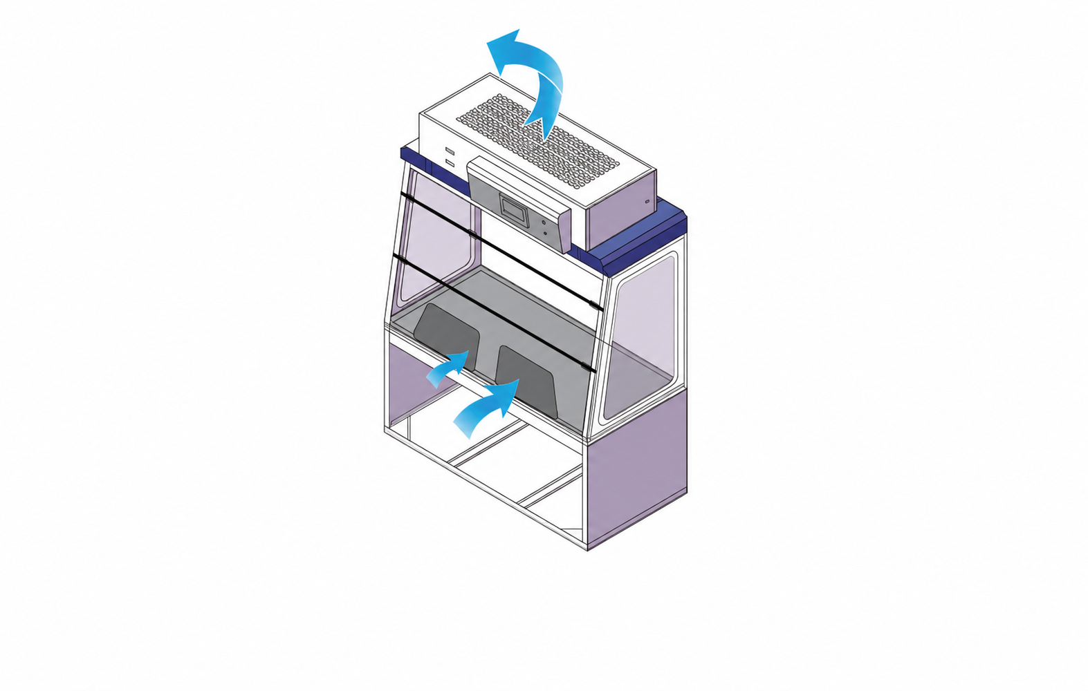
The diagram establishes the direction of travel, not a universal filter stack. For the quotation, identify the contaminant form at each operating step and state whether the filter train is intended for vapors and gases, airborne particles or both. That decision determines the media type, stage order, expected resistance, monitoring method and service procedure.
Molecular Carbon Filtration for Vapors and Gases
Activated carbon and other molecular media remove selected gases and vapors by adsorption or a media-specific chemical interaction. The correct question is not simply whether the hood contains carbon. The buyer must identify each chemical, carrier solvent, concentration, amount, temperature, generation rate, duration and frequency so that the media formulation and quantity can be evaluated against the expected load. Humidity, competing vapors and mixtures can change how available capacity is used.
General-purpose carbon may be suitable for some reviewed organic-vapor applications, while acid gases, ammonia, formaldehyde or other contaminant groups can require treated or purpose-selected media. These labels describe selection directions, not automatic compatibility. The approved filter schedule should state the media grade, mass or cartridge quantity, stage arrangement and the basis used to determine replacement. A process that changes chemicals or operating frequency should be reviewed again rather than carried forward under the original filter name.
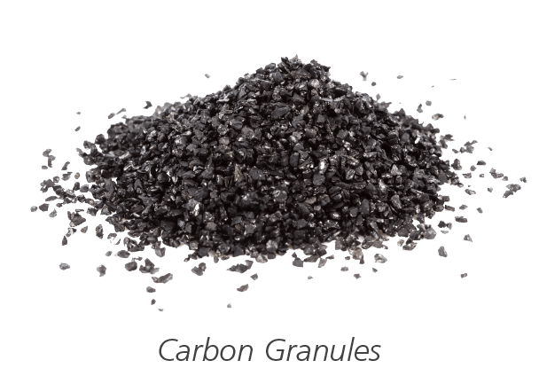
For a molecular-filter configuration, provide the full chemical list rather than a broad description such as solvent work or acid work. The same visible granules can use different impregnation and manufacturing specifications, and two filters of similar dimensions can have different media mass and service capacity. The ductless fume hood schedule therefore identifies the selected media and quantity instead of asking the image or color of the filter to carry a technical claim.
HEPA Filtration for Particulate Loading
HEPA filtration is evaluated when the process releases compatible airborne particles, powders or aerosols that can be captured by a particulate filter. It does not remove a chemical vapor merely because both contaminants arise in the same task. The particle type, size distribution where known, quantity, generation method and potential for rapid surface loading should be described before the filter grade and area are selected.
A particulate stage changes system resistance as it loads. The fan and airflow-monitoring arrangement must therefore maintain the defined work-opening condition across the expected service range or provide a clear alarm and response point. If the particulate is reactive, biologically hazardous, pyrophoric, difficult to decontaminate or unsafe to disturb during changeout, the filter housing and replacement method require additional review. A chemical fume hood should not be reclassified as a biosafety cabinet simply by adding a HEPA filter.
Combined Filtration and Stage Order
Processes that produce both vapor and particulate may require a coordinated molecular and particulate filter train. Stage order matters because one contaminant can load or damage the stage intended for another. A prefilter can protect downstream media from coarse dust, while a final particulate stage can address particles generated upstream, but the correct arrangement depends on what enters the hood and how the selected components behave together.
Combined filtration also creates two separate service questions. The molecular stage can approach breakthrough while airflow remains normal, and the particulate stage can create high resistance while the carbon still has available adsorption capacity. The replacement plan should therefore avoid treating the entire stack as one undifferentiated filter. The quotation should identify each stage, its function, its monitoring or calculation method and whether stages can be replaced independently.
Monitoring, Filter Life and Continued Use
A ductless hood needs two kinds of continued-use evidence. The first shows whether the fan, opening and filter resistance still support the required inward airflow. The second shows whether the selected molecular or particulate media can continue to retain the stated contaminant load. These questions are related, but they are not interchangeable: normal airflow can exist after a molecular filter has approached breakthrough, and adequate chemical capacity can remain while a blocked prefilter reduces airflow.
Airflow and Filter-Blockage Signals
An airflow monitor can indicate whether velocity or volume at its measurement point remains above the configured threshold. A differential-pressure measurement can show changing resistance across a filter stage, and fan-status feedback can show whether the fan has been commanded or is running. Each signal answers a limited mechanical question. The ductless fume hood schedule should identify the sensor location, measurement range, setpoint, delay, calibration method and alarm behavior so that users know what condition has actually been detected.
A low-airflow alarm requires a defined response. The operator should stop or secure the process, close or lower the sash when appropriate, prevent further contaminant generation and follow the laboratory’s investigation procedure. Restarting the fan, increasing speed or resetting the alarm is not enough until the cause has been identified. A blocked prefilter, incorrectly installed filter, open access panel, failed fan or unsuitable sash position can produce different corrective actions.
Pressure and airflow trends can support preventive maintenance, but a single value does not prove containment under every work condition. Site verification should use the agreed opening and operating configuration, and periodic checks should consider changes to filter loading, room air movement and apparatus placement. The selected alarm point should protect the required operating condition rather than merely reflect a factory default.
Saturation and Chemical-Breakthrough Evidence
Molecular-filter saturation is a contaminant-specific question. A VOC sensor may be useful for a compatible target or indicator compound, but no general VOC reading represents every gas or vapor. Some chemicals require a different sensor, a sampling method, a calculated replacement interval with a safety factor, or a conservative scheduled change based on validated loading data. The quotation should state which method applies and which substances fall outside it.
Sensor placement also changes meaning. A device upstream of the filter can indicate process loading but cannot directly prove the quality of the return stream. A downstream sensor may detect a target compound after breakthrough, but only if its response range, selectivity, interference and calibration are suitable. Where a dual-point arrangement is proposed, the purpose of each point and the alarm logic should be documented rather than assumed from the number of sensors.
Odor is not a dependable primary monitor. Human sensitivity varies, some hazardous substances have poor warning properties, and odor can appear after a process change that was never included in the original filter assessment. Any unexpected odor, irritation or suspected release should trigger process stop and investigation, even if the displayed airflow remains normal.
Filter Life as a Cumulative-Load Question
Filter life is determined by how much contaminant reaches the media over time and how much usable capacity the selected configuration provides before the replacement threshold. A credible estimate begins with the maximum amount released per operation, the fraction expected to enter the hood, task duration and operating frequency. Temperature, humidity, competing chemicals, particulate loading and idle exposure can alter the result. The same filter can therefore have very different service life in two laboratories.
A calendar interval is useful only after it has been connected to an operating basis. “Replace every twelve months,” for example, has little meaning if one laboratory runs the process daily and another runs it twice per month. Early operating records should compare actual chemical use and run time with the design assumptions. Where loading is uncertain, the initial replacement interval should be conservative and revised only after monitoring or sampling supports the change.
Particulate-filter life is often governed by resistance, airflow or a planned contamination-control limit rather than molecular breakthrough. In a combined configuration, carbon and HEPA stages may reach their replacement points at different times. Spare inventory and maintenance planning should reflect the individual stage rather than assuming that every filter is replaced together.
Applications, Suitability and Product Selection
Application names are useful for finding a starting point, but they do not complete the selection. Solvent transfer, sample preparation, powder weighing and instrument preparation can each produce different vapor, particulate, heat and loading conditions depending on the exact method. A recirculating fume hood is selected from the documented process behind the label, including normal work, startup, cleaning, spills and credible operator error.
Work That May Fit Filtered Recirculation
Defined small- or moderate-quantity handling of reviewed solvents, reagents or staining chemicals may be considered when the target vapors can be matched to an available molecular medium and the release rate remains within the filter plan. Examples can include controlled transfer, dilution, inspection, sample preparation or instrument-side work. These are conditional applications: the chemical identity, concentration, amount, temperature and frequency determine whether the actual task fits.
Compatible powder or particulate work may be considered with an appropriate particulate stage when the material can be handled and the loaded filter can be changed safely. A combined configuration may be evaluated when a task produces both reviewed vapor and particulate. The selection must address each contaminant form separately, because a molecular stage does not capture particles by adsorption logic and a particulate stage does not remove gases or vapors.
Full-size ductless fume hood configurations are useful when the task requires a fixed laboratory station, a wider chamber, coordinated base storage or more apparatus space than a portable enclosure. The larger cabinet does not increase chemical suitability by itself. It changes the work envelope, filter area and possible configuration, all of which still need to be matched to the process and maintenance plan.
Processes That Require Ducted or Special-Purpose Exhaust
Choose outdoor exhaust when the contaminant cannot be retained by the proposed media, the process load is too high or unpredictable, the room must not receive a treated return stream, or a reliable breakthrough response cannot be established. Continuous evaporation, large open solvent surfaces, uncontrolled reaction products, high heat release and rapidly changing chemical inventories are warning conditions. A building exhaust route can also be preferable when the laboratory cannot manage frequent filter replacement or hazardous changeout.
Perchloric-acid work can require a dedicated perchloric acid fume hood with wash-down and exhaust provisions selected for deposit control. Heated corrosive digestion should be evaluated in an acid digestion fume hood with appropriate exposed materials and exhaust treatment. Radioisotope handling belongs in a radioisotope fume hood review that addresses decontamination, shielding interfaces and waste routes.
A defined hazardous location or flammable atmosphere requires an explosion-proof fume hood and complete electrical and ventilation assessment; a fan or control component described as explosion-proof does not establish the rating of an entire ductless assembly. Unknown biological agents, sterile product protection and clean-air product work should be directed to equipment designed and validated for those purposes rather than reassigned to a chemical filtered hood.
Process-First Selection Sequence
Begin by listing every chemical and particulate that can enter the hood during normal operation, cleaning, maintenance and a credible spill. Record physical form, concentration, maximum amount, temperature, generation rate, task duration and frequency. Where a reaction occurs, include expected products and carrier materials rather than listing only the starting chemicals. This inventory establishes whether filtered recirculation remains a valid direction.
Next, match each contaminant to a capture mechanism and identify any component that the proposed filters do not address. For the remaining process, estimate cumulative loading and define the method used to recognize airflow loss, particulate loading and molecular breakthrough. State the alarm response and replacement criteria before comparing cabinets. If those fields cannot be defined, the selection should return to a ducted or special-purpose exhaust strategy.
Then size the chamber around the apparatus and work sequence. Choose the reference width that provides loading clearance, normal hand access and space around the equipment for airflow. Confirm the sash arrangement, worktop, base, utilities, room-air discharge zone and filter-removal route. Finally, align the fan, filter resistance, power supply, monitoring package and laboratory procedures in one technical schedule.
Information Required for a Project-Ready Quotation
Provide a process sheet for each distinct task. It should include the complete chemical list, Safety Data Sheets where available, concentration, maximum quantity, physical state, operating and peak temperature, generation or evaporation method, duration, daily or weekly frequency, aerosol or powder load and any reaction products. Identify which processes can occur at the same time and whether the hood is shared between departments.
Add the largest apparatus dimensions, desired cabinet width, room plan, ceiling height, nearby supply diffusers, required worktop and base arrangement, utilities, site voltage and available service clearance. For filter lifecycle planning, state the preferred monitoring method, alarm interface, logging or communication requirement, expected maintenance staffing, replacement access, spare-filter policy and used-filter disposal route.
The returned configuration should identify the proposed cabinet and chamber size, molecular and particulate stages, media designations, stage order, fan and airflow basis, monitoring functions, electrical supply, service direction and included accessories. It should also state the operating assumptions and process limits used for selection. These fields allow the buyer to compare configurations on the same technical basis and identify any process that still requires a different enclosure before the order is approved.
Installation, Commissioning and Lifecycle Planning
A ductless cabinet avoids a conventional outdoor exhaust connection, but it still requires coordinated installation. The hood must receive stable electrical power, unobstructed inlet and return-air paths, a usable work zone and safe filter-service access. Commissioning then verifies the delivered configuration against the process and establishes the values, alarms and records that users will rely on during operation.
Placement and the Room Return-Air Boundary
Locate the hood away from doors, busy circulation routes, open windows and strong supply-air jets that can disturb inward flow at the sash. Check the top discharge against ceiling features, shelves, sprinklers, lighting and air diffusers. Returned air should be able to mix with the room without being directed immediately toward an occupied breathing zone or short-circuited back into the hood opening.
The room ventilation system remains relevant because the filtered stream returns indoors. Confirm room volume, normal air-change strategy, occupancy, background contaminant limits and the response to an alarm or suspected release. If site rules require the contaminant to be discharged outdoors or the room cannot accept the return-air condition, a recirculating configuration is not solved by moving the cabinet to another wall.
Set the cabinet level and stable, and check the floor or supporting base for the complete operating load. Maintain the required clearances at side and rear access panels as well as above the filter housing. The installation drawing should show the closed product envelope, sash movement, apparatus loading route, operator position and filter-removal path so that these functions do not compete for the same space.
Commissioning and Alarm-Response Checks
Commission the hood in its final room with the specified sash opening and representative apparatus arrangement. Verify fan operation, direction of inward airflow, the selected airflow or velocity value, filter seating, access-panel closure and unobstructed return discharge. Record the instruments, measurement locations and operating conditions used so that later checks can reproduce the same basis.
Test each supplied alarm and indicator by creating the condition or using the approved functional test method. Confirm the displayed message, audible and visual behavior, remote output where included, reset requirement and operator action. An airflow alarm, pressure alarm and chemical-condition alarm should not be given the same generic response if they represent different failure modes.
Review the installed filter designations against the chemical assessment and verify that the stage order matches the approved schedule. Establish the initial operating record, filter installation date and baseline monitoring values. Users should receive a concise operating procedure covering sash position, permitted processes, prohibited changes, alarm response, pre-use checks and whom to contact when the process or chemical inventory changes.
Filter Change, Handling and Disposal
Plan filter replacement before the first loaded cartridge is removed. The procedure should address process shutdown, access isolation, residual contaminant, protective equipment, temporary containment, lifting, surface cleaning and packaging. Where exposure can occur during changeout, the maintenance method may require local extraction or another engineered control independent of the hood’s normal operating fan.
Used filters should be characterized from the chemicals and materials they captured. Mark the package with the hood identity, filter stage, removal date and known contaminant information, then route it through the laboratory’s hazardous-material or waste procedure. Do not rely on the filter’s external appearance to decide whether it is clean or exhausted.
After a new filter is installed, inspect seals and orientation, close the housing, restart the unit and repeat the applicable airflow and alarm checks. Update the maintenance record and replacement baseline before releasing the hood for process work. Periodic review should compare actual use with the original loading assumptions and include the room, return-air path and service access, not only the filter itself.
Related Laboratory Fume Hood Options
Use the process boundary to compare products rather than treating every laboratory enclosure as a size variant. The complete laboratory fume hood range includes ducted, filtered, compact and special-purpose directions for different contaminants, apparatus and building conditions.
Ducted Full-Size Fume Hoods
A general-purpose steel fume hood sends captured air to a building exhaust and discharge system. Evaluate this route when the contaminant should not return to the room, loading is too high or variable for a practical filter plan, or the laboratory prefers centralized exhaust and treatment. A PP laboratory fume hood provides a separate material direction for reviewed corrosive exhaust applications; polypropylene construction does not by itself determine the correct airflow or chemical process.
Portable Benchtop Ductless Fume Hoods
A portable benchtop ductless fume hood is evaluated when the same filtered-recirculation boundary can be satisfied but the buyer needs a smaller work zone, benchtop placement or movement between defined positions. It should not be selected merely because it is easier to place. Chemical assessment, room-air review, monitoring, power and filter change remain necessary, while chamber capacity and service clearance become more restrictive.
Special-Purpose Laboratory Fume Hoods
Choose a purpose-built page when the process introduces a requirement that filtered recirculation cannot address reliably. Options include a perchloric acid fume hood for wash-down and deposit-control review, an acid digestion fume hood for heated corrosive work, a radioisotope fume hood for decontamination and waste-route coordination, and an explosion-proof fume hood for projects with a defined hazardous-location assessment. The ductless fume hood name is a starting point; the complete process and building system still control final selection.
Frequently Asked Questions
What is the difference between a ductless and a ducted fume hood?
A ducted hood moves captured air through building ductwork to an outdoor discharge or treatment system. A ductless fume hood uses an integral fan and selected filters, then returns the treated stream to the laboratory. The ductless route avoids a conventional exhaust connection but requires stronger process qualification, filter monitoring, replacement planning and room-return review.
Should a ductless fume hood use carbon, HEPA or both?
The contaminant form determines the direction. Molecular carbon or another selected adsorbent is evaluated for compatible gases and vapors. HEPA filtration is evaluated for compatible airborne particles. A process producing both forms may need a combined arrangement with a documented stage order. The chemical list, particulate load and operating pattern must be reviewed before any of these options is specified.
How long does a ductless fume hood filter last?
There is no universal service life. Molecular-filter life depends on media formulation and mass, chemical identity, concentration, amount, temperature, humidity, generation rate, duration and frequency. Particulate-filter life also depends on loading and resistance. The project should define an initial replacement basis, a monitoring or calculation method, a safety margin and operating records that support later adjustment.
Can one filter package handle every laboratory chemical?
No. A filter package is selected for a documented contaminant range and loading condition. Unknown mixtures, new reaction products or a process change can fall outside the original assessment. Introduce a new chemical only after its compatibility, loading, monitoring and replacement implications have been reviewed. Where no defensible filter solution exists, use a ducted or special-purpose enclosure.
Contact the XICHENG Engineering Team Today
Send the chemical inventory, operating quantities, release or evaporation conditions, particulate load, task frequency, apparatus dimensions, room layout and preferred monitoring method. XICHENG will use these inputs to prepare a ductless fume hood configuration covering the cabinet size, filtration stages, fan and airflow basis, monitoring scope, service access, operating limits and pricing within 24 hours.
Shenzhen Office: No. 34 Zhenxing Road (Shengtaian Heavy Industrial Park B), Loucun, Guangming New Dist, Shenzhen, Guangdong, China
WhatsApp: +86 181 2647 8161
Engineering Mailbox: fanalax34@gmail.com