


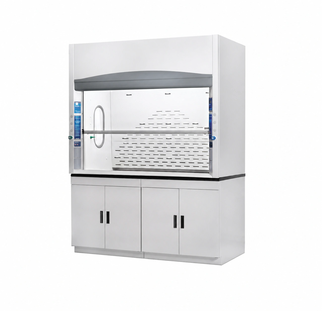
Description
A low flow fume hood is selected when the laboratory needs to reduce conditioned-air exhaust while preserving a defined containment objective. This requires more than operating a conventional hood at a lower fan setting. The sash opening, entry profile, sill or airfoil, baffle and bypass arrangement, internal geometry and exhaust path must work together at the scheduled airflow condition.
The made-to-order, externally ducted hood family is configured for general chemical laboratory work. Each configuration is developed around the required cabinet width, usable opening, laboratory process, exhaust connection and verification basis. The final technical schedule states the dimensions, airflow, static pressure, controls and test condition that apply to the offered hood; the family name alone does not assign one universal operating value to every size.
The distinction matters because three different approaches can reduce exhaust demand. A purpose-designed hood may contain at a lower face velocity. A restricted working opening may reduce the face area while maintaining the selected velocity. A VAV system may reduce exhaust as the sash closes or the operating mode changes. These approaches can be combined, but they do not provide the same evidence and should not be treated as interchangeable specifications.
Low-Flow Fume Hood Product Overview
The high-performance configuration is intended for projects that define both an exhaust objective and a containment-verification method. Laboratory planners can then compare the cabinet, opening, exhaust and control fields as one system rather than purchasing a hood shell and asking the ventilation contractor to establish the performance afterward.
What This High-Performance Hood Configuration Is
The hood provides a ventilated work enclosure between the laboratory and the building exhaust system. Room air enters through the open sash plane, passes around the work zone and moves toward the rear and upper exhaust path. The geometry is arranged to limit disruptive recirculation near the opening and to guide contaminated air away from the operator before it enters the duct connection.
Lower exhaust demand is useful only when it is tied to a specific operating condition. For that reason, the project schedule should identify the working and maximum sash openings, the corresponding exhaust volume, the available static pressure and the test or acceptance condition. A face-velocity value without the opening dimensions does not reveal the total exhaust flow, and neither value alone demonstrates containment.
The hood can be coordinated with constant-air-volume or variable-air-volume control. In a CAV arrangement, the scheduled exhaust condition remains substantially fixed while the hood’s bypass and sash behavior influence the airflow profile. In a VAV arrangement, a sash or face-velocity input can command a damper or air valve as the opening changes. In both cases, the cabinet geometry still has to perform at the defined operating points.
Construction is selected as part of the complete configuration. Exterior panels, liner, baffle, work surface, sash glazing, service fixtures and exhaust components encounter different chemical, thermal and cleaning conditions. The most suitable combination depends on the process list and contact pattern; a general statement such as “chemical resistant” is not enough to select every exposed component.
Product Selection Summary
Select the low flow fume hood family when reduced exhaust demand is a stated project objective and the hood configuration will be evaluated under a defined operating and containment condition. The decision should be based on the offered cabinet, sash opening, exhaust schedule and verification plan together. A lower fan setpoint or a smaller routine opening, considered by itself, is not enough to establish the same product requirement.
The first comparison should therefore identify the required performance condition rather than starting with a cabinet width or control brand. Once that condition is clear, the buyer can determine whether the project needs a purpose-designed low-velocity cabinet, a reduced working opening, VAV setback, or a combination of these measures.
When to Choose a Low Flow Fume Hood
The low-flow/high-performance configuration is a strong candidate for new laboratories and major renovations where conditioned-air exhaust is a significant part of the mechanical load. It is most useful when the laboratory team can coordinate the hood specification with the exhaust, make-up-air and control design instead of treating those scopes as separate purchases.
It also fits projects that need a clear operating opening. The sash can provide a larger opening for setup or equipment movement while the routine working position is defined for normal use. The schedule must distinguish these positions because the exhaust demand and the applicable performance evidence may differ at each opening.
A project may choose CAV when a stable exhaust condition and simpler control arrangement are preferred, or VAV when the flow should follow sash position or operating mode. Either approach can be evaluated with the low flow fume hood family. The decisive question is whether the proposed cabinet and complete ventilation arrangement meet the required acceptance condition at each scheduled mode.
The low flow fume hood is intended for general chemical handling where externally ducted ventilation is the correct control method. Typical work can include bench-scale preparation, mixing, transfer and reactions that release vapors or gases, provided the selected construction matches the actual chemical and thermal exposure. The process review remains necessary because a high-performance airflow design does not make every liner or work surface suitable for every reagent.
Select a Different Fume Hood When
Special hazards should lead the selection before the energy objective. Heated or concentrated perchloric acid work requires a dedicated Perchloric Acid Fume Hood with the applicable wash-down and exhaust provisions. Sustained hot acid digestion may require an Acid Digestion Fume Hood whose exposed construction is selected around the acid, temperature and duty cycle.
Radiological work may require easy-decontamination surfaces, load and shielding coordination, and a controlled exhaust path beyond the general-chemistry configuration. Flammable-vapor projects may also need a hazardous-location electrical design and an Explosion-Proof Fume Hood review. These are product-level requirements; adding an airflow monitor or reducing exhaust does not satisfy them.
Tall distillation columns, reactors or large apparatus can require greater internal height, sash travel and service routing than a standard benchtop format. A distillation or floor-mounted hood should be evaluated when the apparatus envelope controls the design. The buyer should not enlarge the sash opening after selecting a low-flow configuration and assume that the original airflow and test condition still apply.
A ductless hood is a different solution when air is filtered and returned to the room. It is selected from a complete chemical inventory, concentration, quantity and filter-management plan. The low flow fume hood is externally ducted and does not use filter retention as its primary control mechanism.
Information Needed Before the First Technical Comparison
Before comparing configurations, provide the process description, chemical list, expected temperature, preferred width, apparatus envelope, working and maximum sash openings, desired operating modes, available static pressure and the laboratory layout. Include any owner or EHS requirement for face velocity, ASHRAE 110 testing, tracer-gas acceptance, cross draft, alarms, BMS communication or automatic sash behavior.
These inputs do not need to be final construction documents at the first inquiry, but they must be specific enough to avoid comparing unlike products. The next section converts them into the specification and performance fields that should appear in the technical schedule.
Key Specifications, Openings and Performance Evidence
The key specification for a high-performance fume hood is not one face-velocity number. A usable schedule connects the offered cabinet and sash geometry to the operating opening, exhaust volume, hood static pressure, room condition and containment-verification method. These fields allow the mechanical designer to size the exhaust system and allow the buyer to determine exactly what the performance statement covers.
Product-Family Configuration Fields
| Specification Field | Available Product-Family Configuration | What the Final Schedule Must State |
|---|---|---|
| Installation format | Benchtop, externally ducted hood body with project-selected base support | Overall assembly, work-surface height, base cabinet or support and room interface |
| Nominal cabinet width | Made to order for the laboratory layout and apparatus | Approved external and internal dimensions for each hood tag |
| Sash configuration | Vertical or project-selected access arrangement | Glazing, travel, working opening, maximum physical opening and any stop or interlock |
| Interior construction | Selected liner, baffle and work-surface combination | Material for each exposed component and the reviewed process conditions |
| Exhaust connection | One or more project-sized duct connections | Quantity, shape, dimensions, material, location and connection detail |
| Operating modes | CAV, VAV or a defined multi-mode exhaust sequence | Normal, setup, occupied, setback and emergency conditions that apply |
| Airflow monitoring | Optional local monitor, alarm and control interface | Measured variable, sensor location, setpoint, alarm action, power and communication |
| Performance verification | Project-defined factory and/or installed test basis | Test mode, sash condition, face velocity, exhaust flow, release rate, cross draft and acceptance criterion |
| External system scope | Coordinated with remote fan, ductwork, make-up air and controls | Supplied items, field-supplied items, connection points and responsible trade |
This format prevents optional fields from becoming accidental promises. For example, `VAV available` does not mean that a valve, controller, sash sensor and BMS integration are included in every hood. The selected hardware and the corresponding sequence must be listed for the individual project.
Sash Opening, Face Velocity and Exhaust Volume
Exhaust volume is determined by the open face area and the average velocity through that area, with additional interpretation needed for the hood’s geometry and measurement method. When the sash rises, the opening area increases. Holding the same average face velocity across the larger area therefore requires more exhaust. Lowering the sash can reduce the required volume, but only if the operating procedure and control system maintain the scheduled condition.
Every airflow entry should identify the opening width and height used for the calculation or measurement. A schedule that says only `60 fpm`, `0.3 m/s` or `700 CFM` cannot be compared reliably because the missing opening may represent a different cabinet width or sash position. The same rule applies when values are given for normal, setup and emergency modes.
A purpose-designed low velocity fume hood may be evaluated at a larger opening and lower face velocity than a conventional restricted-opening design. Those are distinct claims. The test record must show the actual opening and velocity; results should not be extended to a larger opening or lower velocity that was not evaluated.
ASHRAE 110 and SEFA Reporting Fields
ASHRAE 110 provides a method for evaluating fume-hood performance using airflow visualization, face-velocity measurements and tracer-gas testing. The method does not turn every hood with the same face velocity into the same product, and the phrase `ASHRAE 110 certified` should not replace the actual test condition and result.
SEFA 1-2026 identifies a low-velocity (high-performance) test at 60 fpm (0.3 m/s) or less and requires the applicable maximum physical sash opening for the defined sash type. This is a standard evaluation boundary, not an unconditional statement that every low flow fume hood configuration has passed at that value. The offered configuration must be connected to its own applicable documentation.
| Performance Record Field | What It Describes | Buyer Check |
|---|---|---|
| Hood identification | Manufacturer, model, size, construction and sash type evaluated | Confirm it matches the offered hood or clearly states the covered family |
| Test mode | As-manufactured, as-installed or as-used condition | Confirm the mode required by the owner or EHS specification |
| Sash position and opening | Physical width and height of the face during the test | Compare it with both normal working and maximum project openings |
| Average face velocity | Measured inflow velocity across the defined opening | Read it together with opening area and exhaust volume |
| Exhaust flow | Air volume at the tested operating point | Use it for branch, fan and make-up-air coordination |
| Cross draft | Air movement near the face that may disturb hood inflow | Compare the test condition with the proposed room layout |
| Tracer-gas release | Release rate and ejector position used to challenge containment | Confirm it matches the specified protocol rather than comparing ppm alone |
| Breathing-zone result | Measured tracer-gas concentration at the mannequin location | Compare with the stated acceptance criterion and test mode |
| Sash movement effect | Response while the sash is moved through the defined procedure | Confirm whether dynamic operation is included in the project requirement |
| Airflow visualization | Observed flow behavior, reverse flow, escape or turbulence indicators | Use with quantitative data to identify unstable regions |
Installed Test Basis
An as-installed evaluation includes the actual duct, fan, room supply air, hood location and control response. It is the appropriate stage for finding field conditions that the cabinet alone cannot control. An as-used evaluation goes further by considering the apparatus and operating arrangement present during use. The project can require one or more stages depending on risk and owner policy.
Construction and Aerodynamic Design Selection
A high-performance hood is selected as a complete construction, not as a generic shell with an airflow label. Exterior panels provide the structural and finished enclosure, while the liner, work surface, sash, entry profile, baffle and exhaust components shape the air path and encounter the process environment. Each item should be specified by component so that material compatibility and airflow geometry remain visible in the approved drawing.
Exterior, Liner and Work-Surface Construction
The exterior cabinet carries the sash, panels and service infrastructure and provides access to mechanical and electrical connections. Coated metal is suitable for many laboratory rooms, but the coating should not be interpreted as the chemical barrier for every internal exposure. The process-facing liner and work surface require their own selection.
Liner suitability depends on what reaches the surface. Vapors, splashes, condensate, heated vessels and cleaning agents create different exposure patterns. A material that performs well against occasional room-temperature splash may not be appropriate for continuous hot condensation. The chemical schedule should therefore state concentration, temperature, frequency and whether contact occurs as vapor, liquid or deposited residue.
The work surface provides equipment support and secondary spill control. A dished edge or raised perimeter can limit the spread of small spills, while service cutouts and sinks create additional joints that must be detailed. Apparatus loads, concentrated point loads and heat sources should be identified before the surface and support arrangement are approved.
Where a chemical or temperature requirement exceeds the selected material, the correct response is to change the exposed construction or select a dedicated hood type. The low-flow airflow objective should never override chemical compatibility.
Sash, Sill and Entry Geometry
The sash defines the operator access opening and acts as a physical barrier. Its frame, glazing, handle and counterbalance must move smoothly through the required travel while maintaining the intended opening geometry. The working height should be clearly marked or controlled so normal operation matches the scheduled exhaust condition.
The sill or airfoil shapes the air entering along the lower edge. A clear, rounded entry can reduce abrupt separation and help room air sweep across the work-surface boundary. Cables, tubing, wipes or stored containers placed across this entry can disrupt the intended path. Cable-management provisions should therefore be planned rather than created by holding the sash open around cords.
Side posts and the sash handle also influence entry flow near the operator. Their geometry should avoid unnecessary blockage and sharp transitions without relying on copied proprietary forms. The offered drawing should show the actual components used on the ordered hood so the test basis and fabricated product describe the same entry arrangement.
Baffle, Bypass and Exhaust Path
The rear baffle distributes extraction across the work zone and guides air toward the exhaust connection. Openings near the work surface help remove heavier or low-level releases, while upper paths address buoyant or warm contaminants. The exact arrangement depends on the hood design; it should not be adjusted in the field without understanding how the change affects airflow distribution.
A bypass provides an alternate air path as the sash position changes. In a constant-volume system, it can limit large face-velocity changes when the sash is lowered. In a VAV system, the bypass behavior and control sequence must be coordinated so the valve or damper does not work against an unintended cabinet flow path. The schedule should identify the applicable operating strategy rather than assuming that every high-performance hood uses the same bypass concept.
The exhaust collar and any transition influence pressure loss and flow distribution at the top or rear of the hood. Connection size, shape, quantity and position must match the offered width and airflow schedule. A field transition that is too abrupt or installed without clearance can add resistance and make balancing more difficult.
Airflow, Exhaust and Control Integration
A low flow fume hood operates inside a complete air system. The cabinet establishes the opening, entry profile, baffle and exhaust path, but the connected duct, control device, fan and room-air system determine whether the scheduled volume and pressure are available in use. These responsibilities must be coordinated around the same operating points; selecting an efficient cabinet does not compensate for an undersized duct, unstable fan control or disruptive room air.
| System Element | Primary Function | Project Information to Confirm |
|---|---|---|
| Fume hood cabinet | Shapes entry airflow and contains the process at the defined sash opening | Opening, configuration, offered exhaust volume, pressure requirement and test basis |
| Airflow control device | Maintains or modulates the branch airflow according to the selected CAV or VAV sequence | Operating range, pressure authority, response, fail state, signal and feedback |
| Exhaust duct and fan | Conveys contaminated air and provides the required extraction pressure | Duct material, routing, losses, diversity, fan duty, discharge and redundancy |
| Room make-up air | Replaces exhausted air without creating excessive cross drafts at the hood | Supply diffuser type, location, throw, room balance, door transfer and operating modes |
| Airflow monitor and alarm | Indicates the selected operating variable and warns of a defined unsafe condition | Measured variable, setpoint, delay, alarm outputs, calibration and user response |
| BMS or laboratory controls | Coordinates commands, status, alarms and occupied or emergency modes | Point list, protocol, sequence, trend data, interlocks and responsibility matrix |
Cabinet Performance Versus CAV or VAV Control
A constant-air-volume arrangement holds a scheduled branch flow through the normal operating mode. As the sash position changes, the hood bypass and cabinet geometry influence how the opening velocity changes. CAV is comparatively direct to balance, but lowering the sash does not automatically reduce exhaust energy when the branch volume remains constant.
A variable-air-volume arrangement changes exhaust flow in response to a defined input, commonly sash position, measured face velocity or a coordinated control sequence. The control device can be a suitable air damper or a Venturi air valve, but its turndown, pressure range, response and material must fit the application. A fast actuator or a wide nominal control range does not by itself establish stable hood containment; sensing, tuning, duct pressure and the cabinet response must work together.
For either strategy, the offered technical schedule should identify the hood opening and airflow condition used for selection. A project may include normal, reduced, setback and emergency modes, but every mode needs an explicit purpose and acceptance criterion. Applying an arbitrary minimum flow solely to reduce energy can leave an unsupported operating condition. Conversely, maintaining the maximum design flow at all times can erase the intended energy benefit.
The sash remains part of the operating strategy. A marked working height provides a repeatable opening for CAV operation, while a sash-position input can support VAV demand. Automatic sash closing may reduce unnecessary open time when the hood is unoccupied, but it does not replace airflow measurement, alarms or containment verification. Mechanical stops, sensors and control logic should be described separately so the operator understands what each feature does.
Exhaust Fan, Ductwork and Make-Up Air Boundary
The exhaust fan is selected from the combined volume and pressure requirements of the connected system. The hood pressure requirement is only one part of that calculation; duct friction, fittings, control devices, treatment equipment and discharge components add resistance. In a manifolded system, diversity and simultaneous demand must be defined so one hood changing state does not destabilize another branch.
Contaminated exhaust ductwork requires material and joint construction appropriate for the air stream. Condensation, corrosive vapor, particulate deposition and cleaning access can govern the design independently of energy performance. The fan discharge must also meet the project ventilation and environmental criteria. A low-flow hood is not a substitute for safe discharge location, plume design or required exhaust treatment.
Room make-up air should replace the exhaust volume without directing a disruptive jet at the hood. High-volume ceiling diffusers placed too close to the opening can produce cross drafts that are not evident from the hood airflow display. Supply temperature, diffuser throw, room pressure and door transfer paths should be evaluated at occupied operating conditions, including when multiple hoods or exhaust devices change state.
Where fan speed follows system demand, the control sequence must preserve adequate branch authority across the operating range. Static-pressure reset, branch airflow feedback and fan minimum speed may all be relevant, but final logic depends on the system architecture. The controls contractor and balancer need the hood operating schedule early enough to commission the fan and branches against real demand states.
Applications, Configuration and Product Selection
The low-flow high-performance fume hood is intended for general chemical laboratory work where an externally ducted enclosure is required and exhaust demand is an important project constraint. Selection begins with the process and hazard, then moves through cabinet size, opening, construction, utilities, airflow and controls. Energy reduction is a design outcome only after those requirements have been satisfied.
Suitable General Chemical Laboratory Work
Typical applications include solution preparation, sample handling, analytical procedures, routine wet chemistry and small-scale processes that release vapors, odors or aerosols requiring ducted capture. The hood can support research, quality-control, teaching and industrial laboratories when the selected liner, work surface and service package match the actual substances and operating temperatures.
Equipment layout should be considered before cabinet depth and opening are fixed. Hot plates, balances, reaction vessels, analyzers and support stands require usable work-surface area plus clearance from the sash plane and rear baffle. A wider cabinet may improve apparatus access, but it also changes the open area and exhaust requirement. Oversizing the hood without an equipment plan can work against the low-flow objective.
Intermittent processes may benefit from a defined reduced or setback mode when the hood is unoccupied and the process allows it. Continuous releases, unattended reactions or heat-generating equipment require a different operating review. The project schedule should distinguish occupied work, unattended process, shutdown and emergency conditions rather than applying one operating label to every use.
Low-flow operation is most credible where the room ventilation design is stable, operators can use a defined sash opening and the project can verify the offered configuration. Laboratories with strong cross drafts, frequently changing layouts or uncontrolled make-up air may need room corrections before a lower exhaust condition can be accepted.
Conditions Requiring a Special-Purpose Hood
A general low-flow hood should not be selected solely because it can be fabricated from a chemically resistant material. Some hazards require a dedicated construction, wash-down arrangement, exhaust strategy or electrical review. The process classification determines whether the low flow fume hood family remains suitable.
The same boundary applies to filtration. An externally ducted hood carries the process air into an exhaust system; it is not automatically a ductless filtered enclosure. If recirculation is proposed, chemical inventory, filter media, breakthrough monitoring and change procedures require a separate product and risk assessment.
Configuration and Customization Sequence
Customization should follow a controlled order. First define the process, hazards, apparatus and operator access. Next select the internal construction and work surface. Then establish the physical cabinet and sash opening. Only after the geometry is known should airflow, pressure, CAV/VAV strategy and room coordination be finalized. Utilities, monitoring, documentation and acceptance requirements complete the schedule.
This sequence prevents attractive but incompatible option combinations. For example, adding a deep sink can alter usable work area and drainage requirements; installing a tall apparatus can change the sash arrangement; choosing a heavy liner can affect cabinet support; and specifying an automatic sash can change sensor, power and control responsibilities. Each option must be reviewed in the assembled hood rather than treated as an isolated catalog accessory.
Available customization can include cabinet width and depth, work-surface height, sash arrangement, liner and surface materials, service fixtures, sinks, electrical services, exhaust connections, base storage, monitor and control interfaces. Availability does not mean that every combination is suitable. The approved drawing and technical schedule should resolve component compatibility and show what is included in the supplied scope.
For replacement projects, the existing opening and utility positions are only the starting point. Duct condition, available pressure, fan capacity, room balance and access for installation should be surveyed. Matching the old external dimensions without checking these conditions can reproduce an existing airflow limitation.
Decision ownership should also be visible. The laboratory user defines the process and operating needs; the safety team reviews hazards and acceptance criteria; the mechanical designer coordinates exhaust and make-up air; the controls designer defines signals and sequences; and the hood supplier translates the confirmed inputs into an offered construction. Recording these responsibilities prevents an unresolved building-system assumption from being buried in the furniture schedule.
Information Required for a Project-Ready Quotation
A project-ready request identifies enough technical conditions to select and price an actual configuration. Where information is not yet available, it should be marked as pending rather than filled with an assumed value. This allows the quotation to separate confirmed scope, proposed values and items requiring design coordination.
Process and Hood Inputs
- Application, process description and whether operation is intermittent, continuous or unattended
- Chemical names, concentrations, quantities, temperatures and expected vapor, splash or condensate exposure
- Heat sources, apparatus dimensions, service loads and required working clearances
- Requested cabinet width, depth, work-surface height, sash type and working opening
- Liner, work surface, glazing, sink and service-fixture requirements
- Quantity, room layout, supporting furniture and installation-access constraints
Exhaust, Controls and Documentation Inputs
- Target operating modes and the performance basis expected at each sash opening
- Available duct connection, measured or calculated static pressure and proposed fan arrangement
- CAV or VAV strategy, airflow-control device, monitor, alarm and sash-control requirements
- Room supply-air layout, room-pressure objective and other variable exhaust loads
- BMS protocol, point list, emergency sequence, fail state and commissioning responsibility
- Required submittals, factory test, installed test, witness, training and documentation language
- Electrical supply, applicable code or project standard, delivery destination and requested schedule
Installation, Commissioning and Performance Acceptance
The approved low flow fume hood configuration must be carried through installation without changing the opening, air path or exhaust assumptions that supported selection. Site acceptance is therefore more than placing the cabinet and checking that the fan runs. It coordinates the room, utilities, duct, controls and operating procedure, then records the condition under which performance was verified.
Duct, Fan and Control Commissioning
The exhaust connection should be installed without using the hood collar to support duct weight. Transitions and elbows must follow the coordinated layout and preserve access for inspection and balancing. Duct leakage, joint construction and material suitability should be checked according to the project exhaust specification before contaminated operation begins.
Balancing starts with the scheduled operating modes and sash openings. The technician should record branch airflow, hood pressure requirement, control-device position and relevant system static pressure rather than adjusting to a single display value. In a VAV system, minimum, normal, maximum and emergency states should be exercised where they are part of the approved sequence. In a CAV system, sash movement and bypass behavior should be observed without changing the balanced branch volume unintentionally.
The fan and duct system should be checked under realistic simultaneous demand. A branch that reaches its setpoint when other hoods are closed may lose control authority when the system is fully loaded. Conversely, excessive available pressure can create noise, unstable control or unnecessary energy use. Fan control, static-pressure reset and branch devices should be tuned as one system.
Control commissioning verifies inputs, outputs and responses. Sash-position sensors should track the actual opening; airflow or velocity sensors should be calibrated for the installed condition; alarms should activate at their defined thresholds and delays; and commanded states should return the expected feedback. Communication points sent to the BMS should be checked at both the local device and the supervisory interface.
Factory and As-Installed Performance Verification
A factory test can document the behavior of an offered hood configuration under controlled conditions. Its report should identify the cabinet, opening, airflow, pressure, room or test setup, instruments, test method and result. A report for a different width, baffle, sash or operating condition may provide design context, but it should not be represented as the result for the delivered configuration.
An as-installed test evaluates the hood in the actual room with the connected exhaust and supply-air systems operating. This matters because diffuser discharge, doors, traffic, equipment loading and system interaction are not reproduced by a cabinet-only record. The acceptance plan should state whether testing occurs before or after apparatus is placed and which room and building operating modes must be active.
Face-velocity readings describe the air entering the opening but do not by themselves demonstrate containment. Where the project specifies a tracer-gas test such as an applicable ASHRAE 110 procedure, the test setup, challenge location, sash movement and pass criterion must be recorded. Smoke visualization can help reveal flow patterns and disturbances, but qualitative smoke behavior should not be converted into an unsupported numerical performance claim.
If an installed result does not meet the acceptance criterion, corrective work should follow the evidence. Possible causes include room cross drafts, incorrect airflow, inadequate pressure, obstructed baffles, unsuitable apparatus placement, sensor calibration, control instability or a cabinet issue. Increasing exhaust volume without diagnosing the cause can raise energy use while leaving the original disturbance unresolved.
Related Laboratory Fume Hoods
Choose the related hood by process risk and equipment envelope, not by a small difference in exhaust volume. The following alternatives address conditions that change the cabinet, materials, access or exhaust-system design.
General Purpose Steel Fume Hood
A general purpose steel fume hood is the appropriate comparison when the project needs conventional ducted chemical containment and does not require a separately documented low-flow operating basis. Compare both options at the same opening, process load and acceptance condition rather than comparing nominal face-velocity labels alone.
Special-Purpose Chemical and Hazard Hoods
Use the perchloric acid fume hood for heated perchloric processes requiring a dedicated wash-down review, the acid digestion fume hood for concentrated hot-acid loading, and the explosion-proof fume hood when the electrical area classification requires a hazardous-location component strategy. These products are not material-option names for the same general hood; each changes the project review.
Frequently Asked Questions
What makes a fume hood low flow or high performance?
A low-flow or high-performance hood uses coordinated sash, entry, baffle, bypass and exhaust geometry to support a defined containment objective at a lower operating airflow than a conventional comparison condition. The name is not proof of performance. The offered cabinet, sash opening, exhaust volume, static pressure, test method and result must be identified together.
Is a VAV fume hood the same as a low flow fume hood?
No. VAV describes a control strategy that changes exhaust flow with demand. Low flow describes the intended airflow and performance relationship of the hood configuration. A high-performance cabinet can be used with an appropriate CAV or VAV system, while adding VAV control to an unsuitable cabinet does not automatically make it a high-performance hood.
Which airflow and pressure values belong in the quotation?
The quotation should identify the working sash opening, face-velocity basis, exhaust volume and hood static-pressure requirement for the offered configuration. Where the project has normal, reduced, setback or emergency modes, values and purpose should be listed for each applicable mode. Fan external pressure and complete system pressure are separate calculations that include downstream components.
How should energy savings be compared?
Compare annual exhaust volume and fan power using the same hood opening schedule, occupied hours, setback strategy, duct pressure, fan efficiency and make-up-air conditioning assumptions. A percentage copied from another project is not a reliable prediction. The useful comparison is a project calculation between the proposed operating sequences, followed by verification of actual control behavior.
Can the low flow fume hood be used for perchloric acid or radioisotope work?
Not by default. Heated perchloric acid requires a dedicated hood and exhaust review that can include wash-down and deposit control. Radioisotope work can require specific surfaces, filtration, monitoring and decontamination provisions. Submit the substance, activity or concentration, temperature and governing requirements so the correct special-purpose configuration can be selected.
Contact the Xicheng Engineering Team Today
Send the planned process, chemical and temperature list, apparatus dimensions, desired sash opening, available duct and fan information, room-air layout, control sequence and required performance-verification basis. The engineering team will return a proposed low-flow fume hood configuration, identified airflow and pressure fields, included controls and documentation scope, outstanding technical questions and commercial quotation.
Shenzhen Office: No. 34 Zhenxing Road (Shengtaian Heavy Industrial Park B), Loucun, Guangming New Dist, Shenzhen, Guangdong, China
WhatsApp: +86 181 2647 8161
Engineering Mailbox: fanalax34@gmail.com