


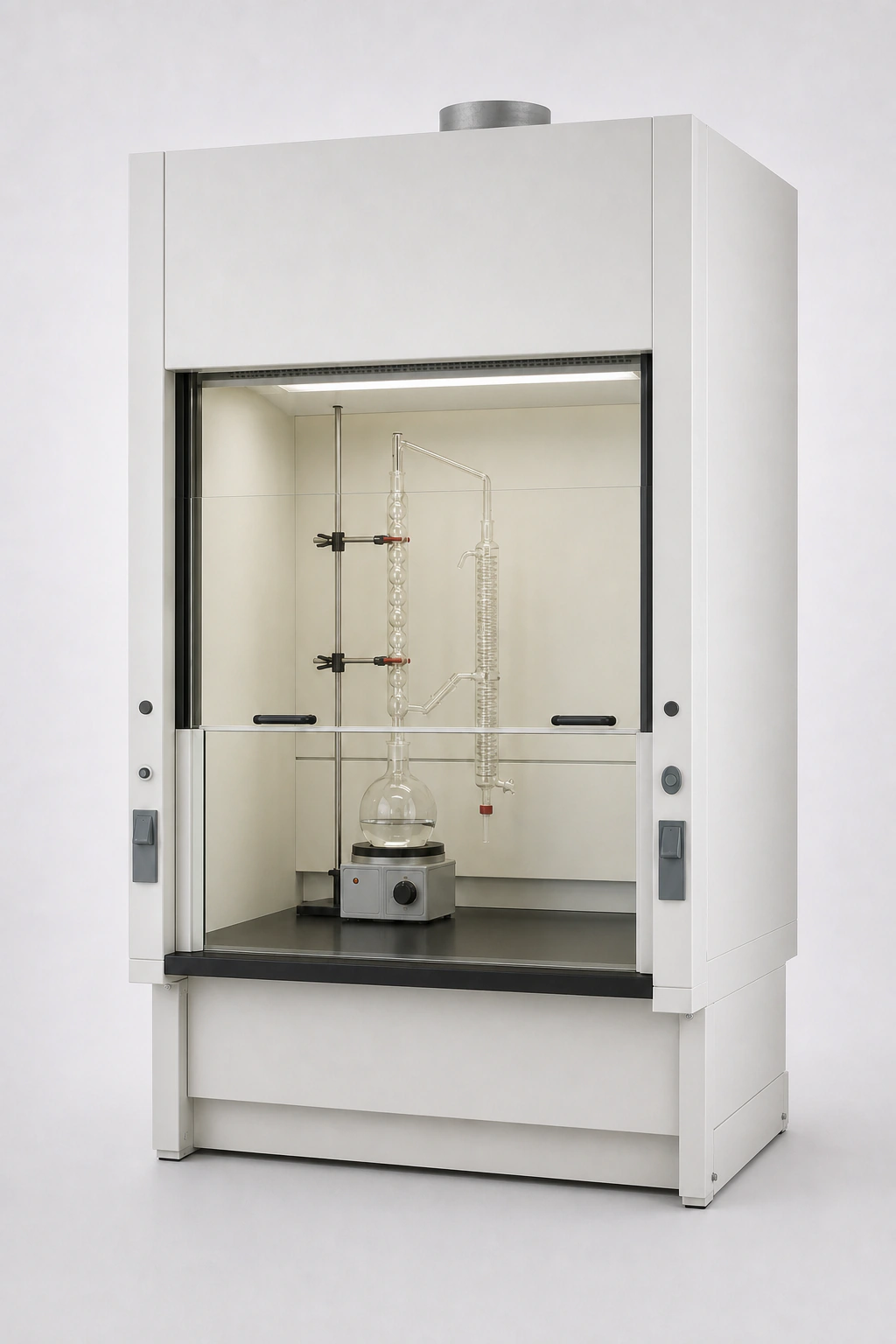
Description
A distillation fume hood is selected when a conventional benchtop hood does not provide enough vertical clearance for the assembled process apparatus. The cabinet combines a tall work chamber with a low or project-selected raised work surface so a flask or reactor, distillation column, condenser, support frame and heat source can remain inside a defined ventilated enclosure.
The distillation fume hood is sized from the complete apparatus rather than the column height alone. Support rods, clamps, vapor lines, cooling-water connections, electrical cords, insulation, receiving vessels and the path used to assemble or remove components all occupy space. If these items are omitted from the layout, a nominally tall cabinet can still be too shallow, too narrow or difficult to operate.
High clearance does not make the hood suitable for every distillation process. Chemical concentration, vapor properties, temperature, heat release and electrical-area classification can change the required liner, work surface, sash glazing, services and exhaust-system design. These conditions are reviewed before the cabinet and control package are finalized.
Distillation Fume Hood Product Overview
The made-to-order product family is configured around four connected decisions: the apparatus envelope, the operator’s setup and working access, the process-facing construction, and the exhaust condition. The approved drawing states the internal clear dimensions and work-surface elevation, while the technical schedule states the openings, airflow, static pressure, controls and verification basis that apply to the offered configuration.
High-Clearance Chamber for Tall Apparatus
The high chamber provides vertical space above a supporting surface. That support surface distinguishes a distillation hood from a walk-in or floor-mounted hood whose primary purpose is to receive floor-supported or roll-in equipment. The work surface may be deliberately lower than a conventional laboratory bench, but it remains a designed load-bearing, process-facing component rather than the room floor.
Internal height is only one part of fit. The reactor or flask needs stable support; the column and condenser require clearance from the ceiling and sash; and the frame must remain clear of the baffle and exhaust path. The front opening must allow the apparatus to be assembled while the normal working opening remains limited to the condition used for ventilation selection.
A full setup opening and a normal operating opening may therefore be different. The larger opening supports installation or maintenance when the process is not active. The working opening supports observation and manipulation during operation and is the condition used for the airflow schedule unless the project states otherwise. Treating the setup opening as the continuous operating position can materially change exhaust demand.
The enclosure width and depth also follow the assembled system. Side clearance is needed for clamps, receivers and service connections, while rear clearance protects the intended air path. Front-to-back depth must account for glassware, support feet and maintenance access without placing the active source at the sash plane. These requirements should appear on a front and side layout before fabrication.
Product Selection Summary
Use the summary below to decide whether a distillation hood is the correct starting configuration before reviewing detailed specifications. A valid selection connects the process, assembled apparatus, work-surface support, sash access and ventilation condition. The distillation fume hood name alone does not resolve any of these fields.
When to Choose a Distillation Fume Hood
Select the high-clearance configuration when the complete apparatus is too tall for a conventional benchtop chamber but can be supported on a designed low or raised work surface. Typical arrangements include laboratory-scale distillation columns, reflux systems, reactors with overhead condensers, extraction trains and preparative columns that need vertical frame space and controlled access.
The apparatus should have a defined, stable support arrangement. The work surface, frame or grid must carry the expected total and concentrated loads without relying on sash tracks, liners or service panels. The equipment can be assembled and maintained through the planned access opening while its normal operating position remains behind the sash plane and clear of the exhaust path.
Fit should be checked in more than one state. A condenser can swing outward during removal, a receiver can require side clearance, and a support frame may be taller during assembly than during operation. Flexible hoses and electrical leads also need movement without pulling across hot surfaces or holding the sash open. The selected cabinet must accommodate these real tasks, not only a static equipment silhouette.
The process chemistry and temperature must be compatible with an available cabinet construction after component-level review. Vapors, condensate, splashes, heated vessels and cleaning agents can affect the liner, baffle, work surface, glazing, seals and exposed fixtures differently. A single material label is not enough to approve the complete hood.
The laboratory must also be able to provide an external exhaust system and room-air condition that support the scheduled opening. The duct, fan and controls are selected with the hood, while the project defines how airflow, alarms and containment will be verified. Where these system inputs are available, the distillation configuration can move from a dimensional concept to an approvable product.
Select a Different Fume Hood When
Use a walk-in floor-mounted fume hood when the equipment must stand on the floor, roll into the enclosure or cannot be supported by a practical low work surface. The distinction is not simply cabinet height: it determines load transfer, access, lower opening geometry and the way equipment enters the enclosure.
Use a conventional benchtop hood when the apparatus fits with suitable clearance above a normal work surface. Adding unnecessary chamber height can increase the setup opening and complicate exhaust, sash and service design without improving the process. The general purpose steel fume hood owns that standard ducted intent.
Use an acid digestion fume hood when hot concentrated acids and thermal/corrosive exposure govern the construction. Use an explosion-proof fume hood when the project hazardous-area classification governs electrical component locations, ratings and installation. A distillation process can involve either condition, but the tall chamber does not satisfy those requirements by itself.
The word “distillation” describes an apparatus and process arrangement, not one universal hazard level. Water purification, solvent recovery and hot-acid preparation present different vapor, temperature, ignition and condensate conditions. The process review must therefore identify the substances and operating states before the geometry is accepted as the governing product choice.
A canopy hood or local heat-exhaust device is not a substitute when the process requires a containment enclosure for hazardous vapors. Conversely, a chemical fume hood should not be selected solely to remove nonhazardous heat when a different ventilation device better matches the risk and process. The EHS and mechanical teams should define the containment objective before the enclosure type is priced.
Key Specifications, Openings and Exhaust Fields
A distillation fume hood specification must connect cabinet geometry to apparatus, access and airflow. External width or total height alone cannot show whether the assembled equipment fits or whether the scheduled exhaust condition applies. The project schedule should therefore state every field below for the same offered configuration and drawing revision.
Project-Confirmed Product Specification
| Specification Field | Selection Basis | Approved Deliverable |
|---|---|---|
| External dimensions | Room layout, ceiling, delivery route, adjacent furniture and service clearances | Overall width, depth and height on the approved drawing |
| Internal clear envelope | Complete apparatus plus operating, assembly, removal and maintenance clearances | Usable width, depth and height with obstructions identified |
| Work-surface elevation | Apparatus height, operator reach, loading method and support structure | Finished elevation and relation to the sash/opening |
| Work-surface support | Total load, point loads, heat source, penetrations and anchoring | Material, thickness/basis, support frame and approved load information |
| Sash arrangement | Setup, operation, observation, emergency access and maintenance tasks | Panel type, travel, working opening, setup opening and stop/sensor provisions |
| Process-facing materials | Chemical, vapor, condensate, splash, temperature and cleaning exposure | Liner, baffle, surface, sill, glazing and exposed fixture schedule |
| Service fixtures | Media, pressure, flow, isolation and equipment connection locations | Fixture type, quantity, location, material and field connection point |
| Exhaust connection | Cabinet width, airflow distribution, duct routing and pressure loss | Outlet quantity, size, shape, material and position |
| Airflow and pressure | Approved opening, operating mode, containment basis and connected system | Exhaust volume and hood static-pressure requirement for each applicable state |
| Controls and verification | CAV/VAV sequence, alarms, interfaces and acceptance requirements | Supplied scope, point list, test method, setup and criterion |
Each line should contain a value, a clear selection statement or an identified pending item. Phrases such as “standard size,” “chemical resistant” or “suitable airflow” are not sufficient for approval because they do not identify the offered construction or the condition used to select it.
Internal Apparatus Envelope
The internal clear envelope is measured after accounting for the sash frame, baffle projection, lighting enclosure, side posts, service fixtures and work-surface edge. These components reduce usable space. A nominal cabinet dimension taken from the exterior can therefore overstate the volume available to the equipment.
A front elevation should show the flask or reactor, vertical column, condenser, support rods and clamps at their operating heights. A side elevation should show depth, service loops, rear baffle clearance and the path for receivers or accessories. Both drawings should include the maximum configuration, not only the apparatus at the beginning of a run.
Clearance must also be maintained around heat sources and moving parts. A heating mantle, hot plate or jacket can require ventilation and service space. Clamps and support feet must not rely on the liner or baffle. Where a component is removed upward, sideways or through the sash, that travel path becomes part of the usable envelope.
The approved drawing should distinguish the physical internal envelope from the recommended equipment zone. A cabinet can provide space near the sash or directly against the baffle that should remain unoccupied during operation. Preserving the entry and rear air paths is more important than filling every available cubic millimeter.
Setup, Working and Maintenance Openings
The setup opening is the access needed to assemble, load or remove apparatus before or after active operation. The working opening is the sash position used while the process is running. A maintenance opening may be required to reach a condenser, upper clamp, light or baffle. These three needs can produce different panel positions.
A multi-panel sash can provide high access without requiring one unusually long moving pane. Vertical panels, horizontal sliding panes or a combination arrangement may be considered according to cabinet width, operator reach and apparatus access. The selected mechanism must remain stable, counterbalanced and serviceable for the actual panel mass and travel.
The airflow schedule should identify which opening is used for normal operation. Full setup access is not automatically an acceptable active-process condition. If the project requires operation at more than one opening, each state needs its own airflow, pressure, alarm and acceptance basis. Sash labels, stops or sensors should correspond to those documented states.
Airflow, Static Pressure and Operating States
Exhaust volume depends on the open area and the selected velocity or containment basis, while the hood static-pressure requirement depends on cabinet and outlet resistance at that flow. These values must be evaluated together. A fan cannot be selected from airflow alone, and a face-velocity value without opening dimensions does not reveal branch volume.
| Operating State | Sash / Opening Condition | Airflow and Pressure Fields | Acceptance Evidence |
|---|---|---|---|
| Normal process operation | Defined working opening with apparatus in its operating position | Scheduled exhaust volume, hood pressure and control setpoint/range | Specified airflow checks and applicable containment method |
| Reduced or setback mode | Closed or reduced opening when permitted by the process | Minimum commanded flow, pressure authority and alarm behavior | Sequence test and confirmation that the mode is permitted |
| Setup / loading access | Large opening with no active hazardous process unless specifically approved | Required fan/control state and any time or procedural limitation | Access procedure and alarm/interlock check |
| Emergency state | Project-defined sash and control condition | Commanded flow, fan capacity, room-air response and fail state | Functional test against the approved emergency sequence |
| Installed acceptance test | Exact opening and apparatus/load condition named in the test plan | Measured airflow, pressure and relevant room conditions | Complete report with instruments, setup, method and result |
Normal Operating Condition
The normal condition should represent the way the apparatus is actually used. Support rods, glassware and services are placed in their operating positions, the sash is at the marked working opening, and the room supply and exhaust systems are in the intended occupied mode. This creates a repeatable condition for balancing, alarms and performance verification.
Apparatus Fit, Construction and Utility Coordination
A distillation fume hood is built around an operating assembly, not around an empty cabinet. The enclosure, work surface, support structure, sash, baffle, services and exhaust connection must be developed from the same apparatus drawing. This prevents a tall column from fitting on paper while its condenser, clamps, heating equipment or service connections conflict with the actual hood.
Complete Distillation Apparatus Envelope
The apparatus envelope begins with the largest assembled operating condition. It includes the flask or reactor, column, condenser, take-off head, receiver, support rods, clamps, heating mantle or bath, hoses, cables and any lifting or removal movement. Glassware height alone is not an adequate sizing input because the support and service components often establish the true width, depth or access requirement.
A front elevation establishes lateral spacing and the relationship between the column and sash panels. A side elevation identifies rear clearance, condenser depth, service loops and the distance between the apparatus and the baffle. A plan view is useful when several vessels, receivers or service connections occupy the work surface. These views should use one scale and one revision so that clearances are not assembled from conflicting sketches.
The apparatus can change shape during use. A receiving flask may be exchanged, a clamp may swing outward, a condenser hose may move, or a component may be lifted above its operating position. The clearance study therefore covers setup, normal operation, sampling, shutdown, cleaning and maintenance. The largest static outline is only one part of the fit assessment.
Work Surface, Support Frame and Load Path
The work surface carries more than the nominal mass of the glassware. The design load includes vessels and process charge, support frames, heating equipment, temporary tools and localized reactions from clamps or anchors. Concentrated loads can govern even when the total mass appears modest. The proposed schedule should identify both distributed and point-load conditions and show where each load enters the support frame.
A low work surface creates the vertical clearance required by tall apparatus, but its finished elevation must still support safe access. Operators need to reach valves, controls, sample points and clamps without leaning through an unnecessarily large opening. If a platform, step or separate access method is required, it belongs in the room and operating review rather than being discovered after installation.
Penetrations for drains, cables or fixed apparatus require coordinated reinforcement and sealing. Their locations should avoid support members, baffle zones and areas that collect spills. Where the apparatus has an independent floor or wall frame, the hood should provide clearance around that structure without transferring unintended loads to the liner or sash frame.
Exhaust, Airflow and Control Integration
The enclosure and exhaust system are selected as one operating arrangement. A high-clearance chamber, tall apparatus and several sash states can produce a different air path from a conventional bench hood. The technical schedule therefore connects every stated exhaust value to a defined opening, apparatus condition, branch pressure and control mode.
CAV and VAV Control Options
A constant air volume configuration maintains the scheduled exhaust quantity for its defined operating condition. It can suit projects with a fixed marked opening and a stable operating sequence. The sash still requires a clear working position because opening the sash beyond the design condition changes the velocity and containment relationship even when fan flow remains constant.
A variable air volume configuration adjusts exhaust in response to the selected control input and operating sequence. Sash position, measured airflow or face-velocity feedback may form part of that strategy. The supplied hood, controller, airflow sensor, air valve or damper, fan and building-management interface must be identified individually; the term “VAV hood” alone does not define which components are included.
VAV operation also depends on available pressure authority and response across the permitted range. The branch device must be able to regulate the required minimum, normal and maximum states without forcing the exhaust fan outside its stable operating region. Setback flow is selected only when it remains compatible with the process state, hood design, room-pressure sequence and project safety basis.
Where a control strategy uses sash position as a demand signal, actual airflow still needs a defined verification method. Position establishes intended opening, not proof of delivered exhaust. Likewise, a fan command or damper position does not by itself confirm branch flow. Commissioning should demonstrate the relationship between command, measured condition, alarm and response.
Exhaust Fan, Ductwork and Room Make-Up Air
The exhaust fan is selected from the total system duty, including hood resistance, duct losses, treatment equipment where present, stack requirements and an appropriate design allowance. The hood static-pressure requirement is one part of that calculation. It should be reported at the same exhaust volume and opening condition used for the distillation fume hood schedule.
Duct routing affects both pressure and maintainability. Outlet quantity and location should align with cabinet width and internal distribution. Transitions, elbows, dampers and flexible connections are coordinated to avoid abrupt disturbances near the hood outlet. Materials are selected against the conveyed air stream and cleaning or treatment requirements, not simply matched to the visible cabinet exterior.
Room make-up air must replace the exhaust without creating disruptive cross-drafts at the sash. Supply diffusers, doors, adjacent hoods, traffic and thermal plumes can influence the entry condition. The room air balance should be tested in representative occupied modes, including other exhaust devices that operate simultaneously.
For laboratories with pressure relationships to corridors or adjacent rooms, the distillation fume hood becomes part of the room-control sequence. A large change in sash demand can affect room pressure and supply response. The controls design should state priority, tracking, response and alarm behavior rather than assuming the hood branch can change independently.
| Control State | Defined Input | Required System Response | Verification | Record |
|---|---|---|---|---|
| Normal operation | Marked working opening and active process state | Maintain scheduled exhaust and applicable room relationship | Airflow/pressure checks and specified hood test | Baseline values |
| Reduced opening | Sash below the normal working limit where permitted | Maintain approved CAV state or modulate within the VAV sequence | Command, measured flow and alarm check | Setback values |
| Setup access | Large opening for apparatus loading or service | Apply the documented fan/control state and operating restriction | Functional sequence and procedural check | Access condition |
| Low-airflow fault | Measured condition below the defined threshold | Issue local alarm and configured remote signal; apply approved response | Simulated or controlled fault test | Threshold and delay |
| Power / communication fault | Loss of power, feedback or network communication | Move or remain in the documented fail state and annunciate fault | Loss-of-signal functional test | Fail-state result |
| Emergency mode | Local or building emergency command | Execute the approved hood, fan, air-valve and room-air sequence | Integrated systems test | Emergency values |
Applications, Configuration and Product Selection
The distillation fume hood is selected when tall apparatus needs an externally exhausted enclosure with a designed low or project-selected raised work surface. The name “distillation fume hood” describes the enclosure geometry and typical process arrangement; it does not by itself establish chemical compatibility, fire protection, explosion protection or containment performance. Those requirements are confirmed from the actual process and project basis.
Suitable Distillation and Reaction Work
This configuration can support tall distillation columns, reflux assemblies, preparative columns, reactors with vertical condensers and other laboratory setups whose assembled height exceeds a conventional bench-hood chamber. It is particularly useful when the apparatus can rest on a defined work surface while the operator needs front access to lower controls, receivers and service connections.
The application review covers every normal and credible non-routine state. Charging, heating, reflux, collection, sampling, cooling, draining, cleaning and disassembly can expose different vapors, temperatures and access needs. The selected liner, glazing, work surface, fixtures and exhaust condition must remain appropriate for the documented sequence, not only for the main solvent or the longest steady-state step.
Scale matters. A taller apparatus assembly can alter support loads, heat release, vapor inventory, service demand and operator reach. Moving a process from a small bench setup into a larger column is not simply a matter of increasing cabinet height. The project should define the process quantity, equipment data, expected emissions and abnormal conditions used for enclosure selection.
Conditions Requiring Another Hood Type
A conventional chemical fume hood may be more efficient when the apparatus fits comfortably above a normal bench-height surface and does not need exceptional vertical access. Using a high-clearance cabinet for ordinary bench work can increase opening area, room-space demand and exhaust-system burden without improving the process fit.
A walk-in fume hood should be evaluated when the equipment stands on the floor, rolls into the enclosure or requires a floor-level installation path. The distinction is functional: a distillation hood provides a designed low/raised work surface for supported apparatus, while a walk-in configuration provides a floor-mounted or open-base equipment zone. Apparatus footprint, loading and access determine the choice.
Other hazards can require a different engineered solution. Processes involving perchloric acid, radioisotopes, high heat, energetic reactions, pressure equipment, explosive atmospheres or biological hazards are not made suitable merely by placing them in a tall enclosure. Applicable facility rules, risk assessment and specialist design determine the required hood construction, wash-down, filtration, fire/explosion features or alternative containment.
A ductless recirculating enclosure should not be substituted solely to avoid ductwork. Filter selection, chemical loading, breakthrough monitoring, operating limits and disposal must be proven for the complete process. The externally ducted distillation fume hood remains part of a building exhaust system and does not treat or neutralize contaminants unless a separately designed treatment system is included.
Configuration and Customization Sequence
Configuration starts with the apparatus and process, then proceeds to enclosure geometry, work-surface support, access, materials, utilities, exhaust and controls. Reversing this order can produce a cabinet that fits the room but not the equipment. The approved layout should be stable before final fabrication dimensions and outlet positions are released.
First, define the complete equipment envelope in operating, loading and maintenance states. Second, establish work-surface elevation, support and penetrations. Third, choose sash panels and opening states that support access while limiting the normal operating opening. Fourth, select process-facing components from the chemistry, temperature and cleaning exposure.
Fifth, coordinate service fixtures, flexible connections and external isolation. Sixth, calculate exhaust volume and branch pressure for the approved opening states and room conditions. Seventh, define CAV or VAV controls, monitoring, alarms, BMS points and failure behavior. Finally, confirm delivery, installation, commissioning, documentation and acceptance responsibilities.
Customization does not mean leaving every field undefined. It means that the offered configuration is documented in a project-specific schedule and drawing. A useful quotation converts project inputs into a proposed size, component schedule, exhaust requirement, control scope and list of unresolved decisions.
Information Required for Project-Ready Quotation
Installation, Commissioning and Lifecycle Verification
Performance depends on the delivered hood, installed apparatus, connected exhaust system, room air distribution and control sequence. Factory documentation establishes the intended configuration, while site verification confirms that the complete system operates under the approved conditions. Installation and commissioning scope should therefore be assigned before shipment rather than after the cabinet reaches the laboratory.
Work Surface, Utilities and Apparatus Installation
The work surface and support frame are levelled, anchored and inspected against the approved load and penetration schedule. Point loads and support feet are placed over the intended reinforced areas. Apparatus must not be anchored to the liner, baffle or sash frame unless a specific engineered attachment is shown.
Utility connections are pressure-tested or electrically verified using the applicable project procedure. Service labels identify media and isolation. Flexible hoses and cables are routed away from hot surfaces, sash mechanisms and primary air passages. Connections retain enough movement for normal apparatus operation without creating loops that can snag during access or cleaning.
Glassware, support frames, condensers, heaters and receivers are installed in the approved operating positions. Clearance to the baffle, glazing, fixtures and opening is checked through setup, operation and removal movements. Heating and electrical equipment are connected only after their power, load, grounding and environmental requirements have been reviewed.
Changes made during installation should be recorded on the final drawing. Relocating a column, adding a support plate or moving a service outlet can alter access and airflow. A field adjustment that appears mechanically minor may invalidate the configuration used to set airflow or perform containment testing.
Duct, Fan and Control Commissioning
The exhaust branch is inspected for material, size, routing, support, joints, transitions, dampers or air valves, flexible connections and access. The fan and any treatment or stack system are checked against the approved system duty. The hood outlet is not used to support field duct loads beyond its intended connection arrangement.
Air balancing begins after the room supply and exhaust systems are available in their representative operating modes. The working sash opening is marked, the apparatus is placed in its agreed test configuration, and branch flow and pressure are measured. For systems with several hoods or room tracking, simultaneous operating conditions should match the design basis.
CAV controls are checked for the scheduled operating state and relevant alarms. VAV controls are tested through permitted sash positions and demand changes, including minimum, normal and maximum states where applicable. The observed response includes measured flow or selected controlled variable, branch device behavior, fan response and room-pressure effect.
Airflow monitors and alarms are commissioned using measured conditions rather than display defaults. Setpoints, delays, units, normal indication, audible/visual behavior and remote points are verified. Sash sensors, stops, emergency commands and automatic sash equipment, when supplied, are tested against the approved sequence.
Factory and As-Installed Verification
Factory inspection can confirm dimensions, construction, sash operation, component schedule, control-panel function and other tests included in the order. It does not reproduce the final room, duct system or apparatus layout unless those conditions are specifically included in an agreed test setup. Factory results and site results serve different purposes and should be labelled accordingly.
As-installed verification uses the project-specified method and exact field condition. The report identifies sash opening, apparatus or loading, room supply/exhaust mode, doors, nearby disturbances, measured airflow and pressure, instruments, calibration status, test procedure and result. A statement that the hood “passed” without the condition and criterion is not a complete acceptance record.
Where an ASHRAE 110, EN 14175 or other recognized test is required, the edition, test type, tracer-gas setup, challenge conditions and acceptance criteria must be named by the project. Mentioning a standard does not create a universal product result. The delivered configuration and site installation are evaluated against the specified protocol.
Corrective work may involve balancing, control tuning, sash adjustment, room-air changes, baffle configuration or apparatus placement. Retesting should use the same documented condition unless the approved basis is formally revised. Final reports capture both the accepted result and the settings that produced it.
Related Fume Hood Configurations
Related products should be compared by apparatus support, hazard basis and exhaust objective rather than by cabinet appearance. The alternatives below address different operating constraints and should not be treated as interchangeable material or size variants of the distillation fume hood.
Walk-In Fume Hood for Floor-Standing Equipment
Select a walk-in fume hood when equipment rests on the laboratory floor, rolls into the enclosure or needs floor-level loading. It provides a large equipment zone without the designed raised work surface used by a distillation enclosure. The room route, floor loading, access opening and equipment service connections become primary selection inputs.
Specialized Hoods for Defined Chemical Hazards
Processes with a defined specialized hazard may require a purpose-specific enclosure. Examples include an perchloric acid fume hood, an acid digestion fume hood or a radioisotope fume hood. Tall apparatus does not remove the construction, wash-down, contamination-control or facility requirements associated with those processes.
Frequently Asked Questions
What is a distillation fume hood?
A distillation fume hood is an externally exhausted laboratory enclosure with a high-clearance chamber above a low or project-selected raised work surface. It is configured for tall supported apparatus such as columns, condensers, reactors and receivers. Final geometry, materials, sash access, exhaust and controls are selected from the complete process and equipment layout.
How is it different from a walk-in fume hood?
The distillation configuration provides a designed work surface and support arrangement for tall apparatus. A walk-in or floor-mounted hood provides a floor-level equipment zone for large or movable equipment. The deciding factors are the equipment support level, loading route, footprint, service connections and required operator access, not overall cabinet height alone.
Which dimensions are required for selection?
Provide the complete assembled width, depth and height in operating, setup and maintenance states. Include support frames, clamps, condensers, receivers, heaters, hoses, cables and component-removal paths. Room dimensions, delivery route, work-surface elevation and operator reach are also required. The approved drawing should distinguish external dimensions from the usable internal envelope.
Can the hood be supplied in different materials?
Process-facing components can be configured from materials selected for the documented chemical, vapor, condensate, splash, temperature and cleaning exposure. The liner, baffle, work surface, glazing, sill, fixtures, fasteners and exhaust transition are reviewed individually. A material option is not a universal compatibility guarantee; the approved component schedule defines the offered construction.
How should the installed hood be verified?
Verification begins with dimensions, apparatus fit, sash function, utilities and exhaust connections. Air balance and controls are then tested at defined openings and representative room/apparatus conditions. Where a recognized hood-performance method is specified, the report identifies the edition, setup, instruments, environmental condition, criterion and result. Final values become the baseline for operation and later change review.
Contact the Xicheng Engineering Team Today
Send the complete distillation apparatus drawing, maximum assembled envelope, support and load details, process chemistry and temperature, required services, room layout, intended sash states, exhaust-system information and control/BMS requirements. Xicheng will use these inputs to prepare a project-specific hood configuration, technical schedule, drawing scope and quotation within 24 hours.
Shenzhen Office: No. 34 Zhenxing Road (Shengtaian Heavy Industrial Park B), Loucun, Guangming New Dist, Shenzhen, Guangdong, China
WhatsApp: +86 181 2647 8161
Engineering Mailbox: fanalax34@gmail.com
Submit the apparatus layout and project requirements for engineering review.