




Key Takeaways
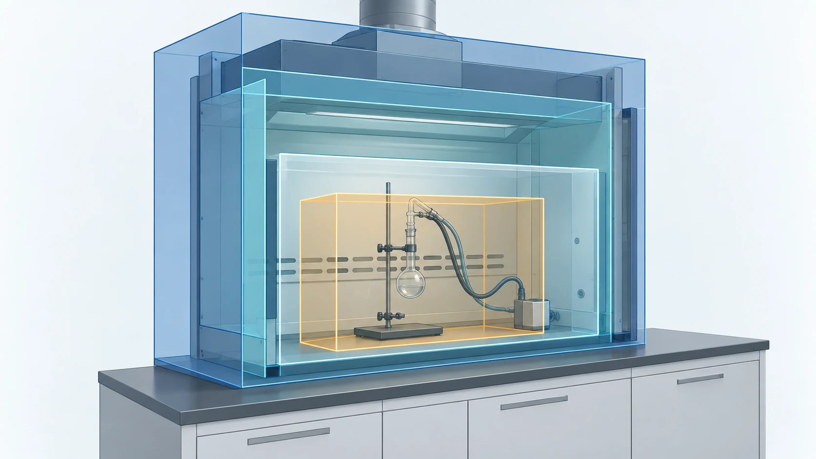
- Chamber clearance sets fume hood size capacity: Standard widths measure exterior panels, leaving interior working space 4 to 10 inches narrower.
- Sash opening dictates exhaust volume: Volumetric demand follows opening area directly (CFM = face velocity × opening area).
- Facility transport paths form hard limits: Doorways, elevators, and corridor turns must be verified before procurement.
Fume Hood Size at a Glance: Three Checks That Set Every Dimension
A chemical fume hood is a ventilated enclosure; selecting the correct fume hood size requires matching apparatus dimensions and sash openings rather than bench length alone. Facility engineers must verify internal clearances, ventilation loads, and transport paths before committing to a cabinet footprint.
| Nominal Width (Cabinet Exterior) | Usable Interior Chamber (W × D × H) | Operational Sash Opening (W × H) | Application Focus |
|---|---|---|---|
| 900 mm | 868 × 650 × 1200 mm (34.2 × 25.6 × 47.2 in) | 868 × 457 mm (34.2 × 18.0 in) | Small-scale synthesis, single hotplates, titrations, compact reagent prep |
| 1200 mm (4 ft) | 960 × 680 × 1150 mm (37.8 × 26.8 × 45.3 in) | 960 × 457 mm (37.8 × 18.0 in) | General organic chemistry, rotary evaporators, single analytical setups |
| 1500 mm (5 ft) | 1260 × 680 × 1150 mm (49.6 × 26.8 × 45.3 in) | 1260 × 457 mm (49.6 × 18.0 in) | Moderate synthetic apparatus, dual stirrer stations, distillation heads |
| 1800 mm (6 ft) | 1560 × 680 × 1150 mm (61.4 × 26.8 × 45.3 in) | 1560 × 457 mm (61.4 × 18.0 in) | Multi-neck flasks, chromatography columns, shared two-operator setups |
| 2400 mm (8 ft) | 2160 × 680 × 1150 mm (85.0 × 26.8 × 45.3 in) | 2160 × 457 mm (85.0 × 18.0 in) | Pilot setups, continuous flow reactors, automated liquid handling systems |
Understanding these standard fume hood dimensions requires evaluating three distinct geometric planes. The nominal exterior width indicates how much laboratory bench or casework wall run the cabinet consumes. However, the usable interior chamber dimensions dictate whether your chemical apparatus physically fits inside. The operational sash opening defines the face area through which laboratory air enters the enclosure.
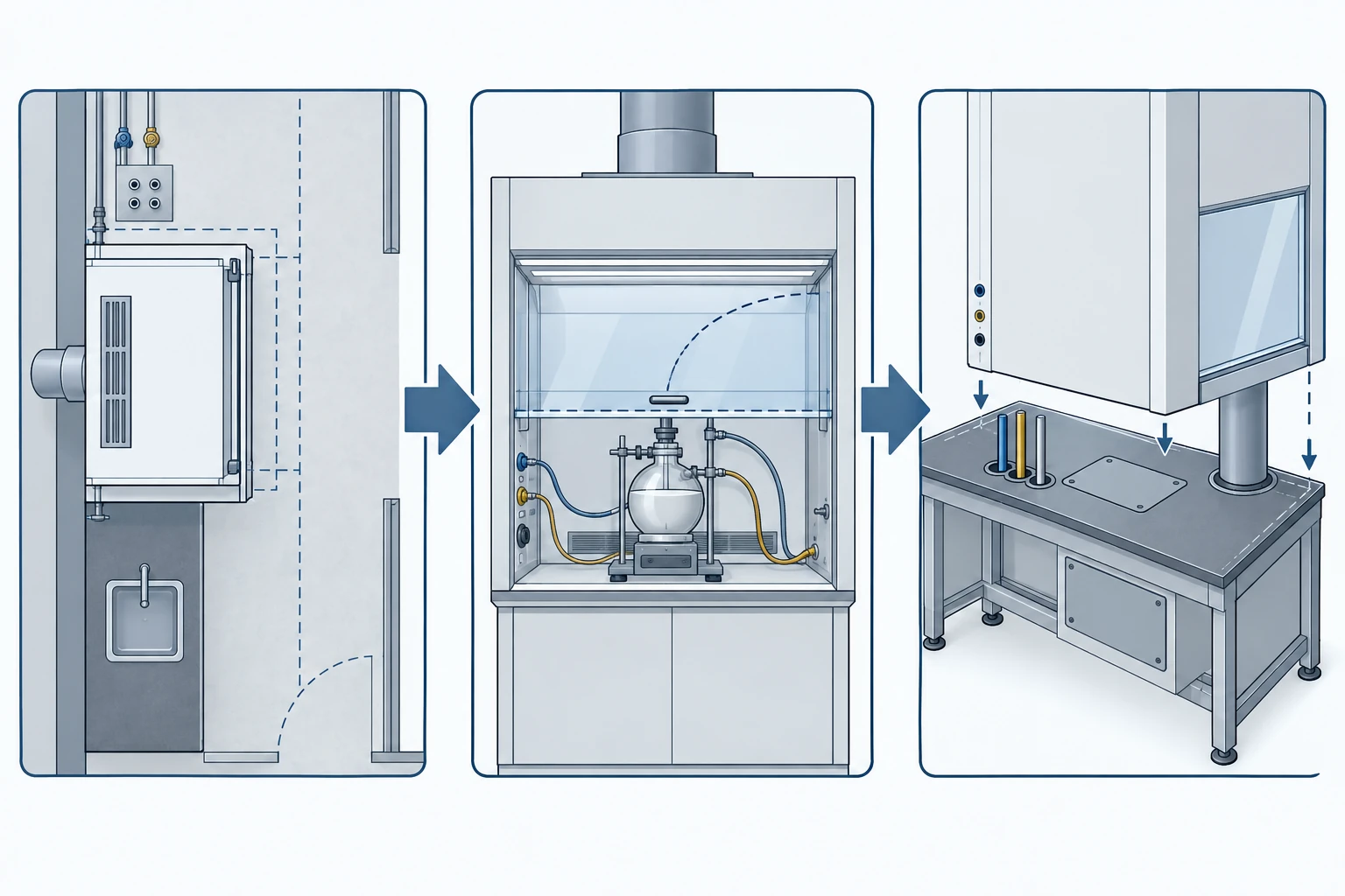
Facility planners must execute three physical checks in sequence before settling on a cabinet specification:
- Apparatus Envelope Check: Measure the outer envelope of your largest glassware assembly or instrument, adding required side, rear, and top safety clearances.
- Ventilation Load Check: Calculate the exhaust air volume demanded by the sash opening at design face velocity, verifying building makeup air capacity.
- Delivery Route Check: Trace the shipping path through building doorways, elevators, and corridor turns to ensure the assembled cabinet reaches its room.
Evaluating these three physical boundaries allows engineering teams to verify exact chamber requirements early in the project schedule. You can now determine the preliminary width category required for your laboratory apparatus before reviewing internal wall profiles.
What Standard Fume Hood Sizes Actually Measure
Catalog classifications for standard fume hood sizes consistently refer to the outer width of the metal or polypropylene cabinet superstructure. When an architect or vendor lists a 4 ft, 5 ft, or 6 ft unit, this measurement represents the extreme exterior boundary from left panel to right panel. It does not describe the unobstructed benchtop area available to the chemist during daily procedures.
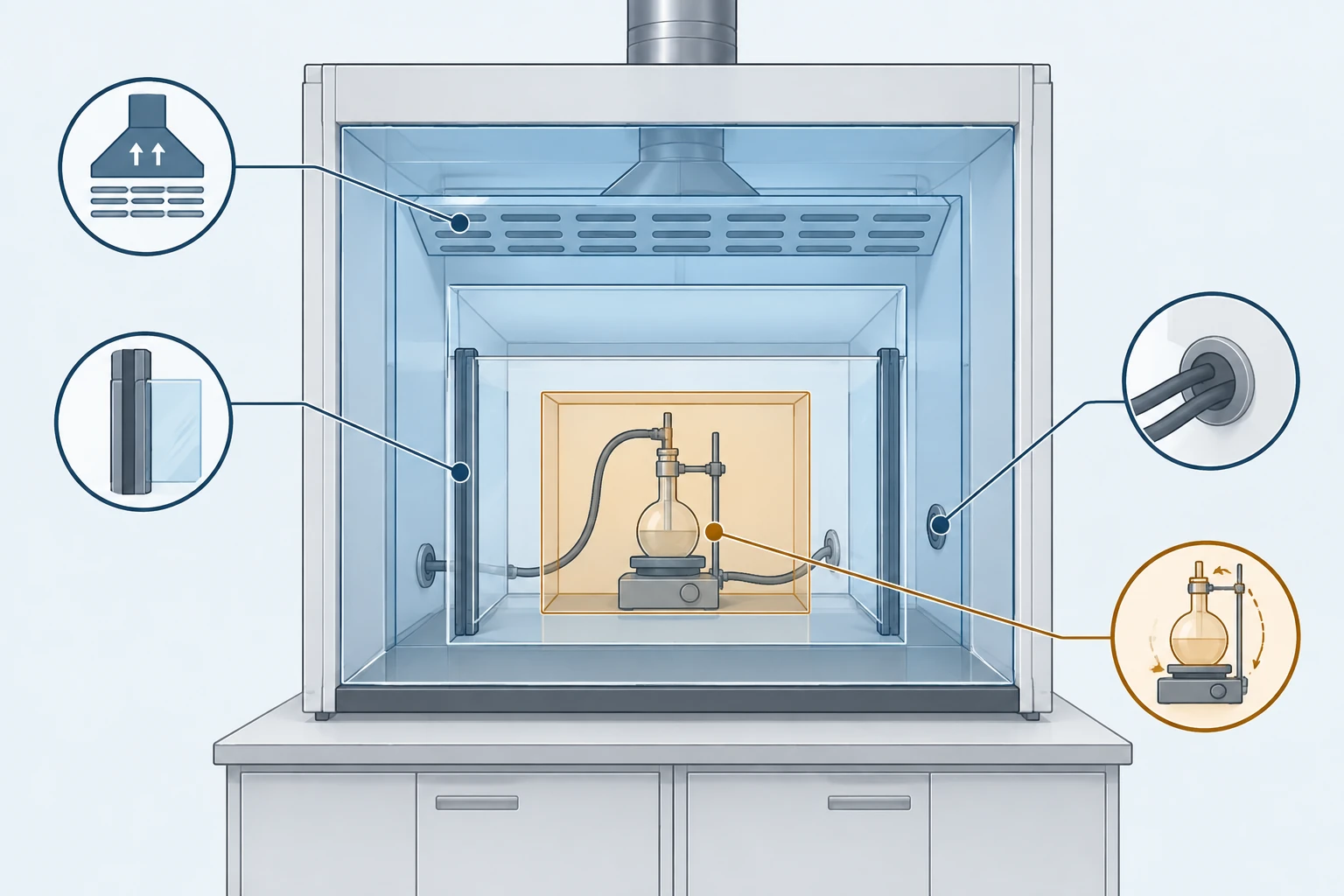
Every chemical fume hood incorporates structural double-wall side construction. These side walls house utility plumbing for nitrogen, compressed air, vacuum, and pure water fixtures. They also conceal remote-control valve linkages, electrical conduit pathways, sash counterweight cable channels, and aerodynamic side airfoils that direct incoming room air smoothly across the threshold. In typical industrial and institutional models, these functional side walls absorb between 4 and 10 inches (100 to 240 mm) of total horizontal span. In seam-welded polypropylene enclosures engineered for harsh acid environments, side walls often feature internal structural stiffening ribs and dedicated vertical bypass channels, which further widen the boundary frame relative to clear benchtop space.
Aerodynamic entry profiles also require dedicated lateral space. Radiused corner airfoils and flush-mount sash guide tracks are engineered to eliminate boundary layer separation as room air accelerates through the opening. When these airfoils are combined with plumbing service chaseways, the usable internal chamber width is substantially reduced. Because side wall thickness varies by manufacturer and material system, two enclosures sharing the same nominal 4 ft width provide noticeably different working envelopes. One manufacturer may feature compact structural posts providing 44 inches of interior width, while another incorporates deep utility chases leaving only 37.8 inches of interior clearance.
As detailed in the SEFA 1-2010 recommended practices, nominal dimensions serve as architectural placeholders while detailed engineering shop drawings define actual chamber volume. Standard benchtop lines cluster around imperial increments of 4 ft, 5 ft, 6 ft, and 8 ft, which correspond to metric modular widths of 1200 mm, 1500 mm, 1800 mm, and 2400 mm, alongside compact 900 mm units.
Selecting a 1200 mm cabinet for a 40-inch analytical instrument leads to an installation failure because the internal width averages only 37.8 inches (960 mm). Engineering teams must inspect detailed cut sheets rather than relying on nominal product codes. In addition, chemical casework must account for rear liner baffles that reduce internal depth. Casework coordinators and HVAC engineers must cross-check architectural wall runs against vendor shop submittals before approving bench layouts. You can determine your true working area only after subtracting structural side wall allowances from nominal cabinet widths.
From Nominal Width to the Usable Apparatus Envelope
Interior depth and interior height are configuration-specific dimensions that do not scale automatically with cabinet width. Upgrading a project from a 4 ft model to a 6 ft model broadens the worktop horizontally but adds zero depth or vertical clearance. Interior working depth is governed by liner architecture and baffle placement, while interior height depends on upper superstructure geometry.
Manufacturer specifications document distinct chamber depths across product lines. Published engineering data from Esco Frontier models lists an internal chamber depth of 682 mm. In comparison, technical documentation from XICHENG polypropylene benchtop models indicates standard internal depths ranging from 650 mm to 680 mm across its primary configuration families. Exterior cabinet depths typically measure 750 mm to 850 mm, meaning front aerodynamic sills and rear exhaust plenums consume substantial space. Total exterior height commonly reaches 2000 mm or 2350 mm in walk-in designs, yet interior vertical clearance in benchtop units is capped between 1150 mm and 1200 mm due to upper bypass chambers and exhaust collar transitions.
To calculate the usable three-dimensional apparatus envelope, engineers must apply systematic clearance deductions:
- Usable Width = Nominal Exterior Width − Structural Side Walls (100–240 mm) − Lateral Airflow Margins.
- Usable Depth = Interior Chamber Depth − Rear Baffle Clearance − Front Sash Setback Margin.
- Usable Height = Interior Chamber Height − Top Baffle Header − Apparatus Insertion Clearance.
Worked Example: Verifying Clearance for a Benchtop Apparatus
Consider a synthetic chemistry research group evaluating whether an existing benchtop enclosure can accommodate a specialized apparatus assembly consisting of a rotary evaporator and heating bath. The complete equipment cluster measures 32 inches wide, 20 inches deep, and 36 inches tall.
The laboratory manager inspects a standard 1200 mm (4 ft) benchtop enclosure. The engineering cut sheet reveals an exterior width of 48 inches (1200 mm), an interior chamber width of 37.8 inches (960 mm), an interior depth of 26.8 inches (680 mm), and an interior height of 45.3 inches (1150 mm).
Subtracting the apparatus width (32 inches) from interior width (37.8 inches) leaves nearly 6 inches of total lateral clearance across both sides. Subtracting apparatus depth (20 inches) from chamber depth (26.8 inches) leaves 6.8 inches of total depth margin. Subtracting equipment height (36 inches) from chamber height (45.3 inches) leaves 9.3 inches of overhead headroom. The equipment fits safely, provided the operator strictly centers the device to preserve the required 6-inch front setback.
Running through this worked example demonstrates how quickly internal tolerances disappear when placing real hardware. You can now determine whether your experimental equipment package fits within a candidate enclosure before finalizing equipment procurement orders.
Matching Apparatus and Working Opening to the Fume Hood Size
Placing apparatus inside a chemical fume hood is not merely a geometric packing exercise; it directly governs containment aerodynamics. Safety standards enforce strict physical setbacks to prevent equipment from disrupting laminar containment airfoils. When chemical apparatus is placed too close to the front sash, incoming air splits erratically, generating turbulent vortices that draw hazardous vapors outward into the breathing zone.
Institutional Environmental Health and Safety (EHS) guidelines across major research universities enforce equipment setback rules. General institutional standards, including Emory and UC Santa Cruz chemical hygiene protocols, require maintaining all experimental apparatus at least 6 inches (15 cm) behind the plane of the sash. In comparison, University of Pennsylvania EHS guidelines specify placing equipment 5 to 10 cm behind the sash while elevating bulky instruments 2 to 3 inches on laboratory jacks or stands. Elevating equipment allows smooth air passage underneath the apparatus directly toward the lower exhaust baffle slot, eliminating turbulent eddies and dead zones. If bulky heating mantles or reaction blocks rest flat on the worktop, they form an aerodynamic dam that blocks high-density chemical vapors from clearing across the floor slot.
Equipment must never block the lower or upper baffle slots, and large assemblies should not touch the rear liner wall. The operational sash opening acts as a governing size input because it connects chamber geometry directly to laboratory exhaust demand. Modern chemical hoods incorporate physical sash stops at an 18-inch (457 mm) working height, preventing operators from raising the glass too high during active procedures. As detailed in the NIH Design Requirements Manual, chemical hoods operate under specific target face velocities, typically documented with an average of 100 fpm. Volumetric air flow is calculated through the relationship:
CFM = Face Velocity (fpm) × Sash Opening Area (sq ft)
When equipment height forces operators to raise the sash from an 18-inch operating height to a 28-inch setup height, the exhaust air volume required to maintain 100 fpm increases proportionately. If the building ventilation system cannot supply this additional makeup air, face velocity drops, risking hazardous vapor escape. For facility managers designing ducted systems, reviewing the fume hood airflow calculation guide is essential to ensure HVAC blowers can support selected enclosure openings. In many high-volume research facilities, the operational sash opening rather than worktop width becomes the limiting mechanical constraint. You can determine your total exhaust burden by multiplying design face velocity by operational sash dimensions before selecting an oversized fume hood size.
How the Mounting Method Changes the Size You Need
The physical mounting method dictates how much building space the enclosure occupies and how apparatus is loaded into the interior. Standard laboratory installations divide between benchtop enclosures and floor-mounted or walk-in enclosures, each serving distinct equipment profiles.
Benchtop enclosures sit on dedicated base cabinets, modular casework, or structural steel frames. A standard benchtop unit requires a work surface depth of at least 30 to 36 inches to support the superstructure securely. Because the cabinet rests on top of the bench, total floor-to-top height ranges from 2100 to 2600 mm, requiring adequate overhead clearance beneath ceiling grids, duct drops, and lighting fixtures. Base casework selections also establish structural load capacity and mechanical integration. Supporting cabinets typically divide between acid storage units with corrosion-proof polypropylene interior liners and flammable storage units fabricated from dual-wall 18-gauge sheet steel with self-closing doors. These base units define the exact countertop height above finished floor while providing dedicated channels for liquid waste drains and vacuum pump exhaust routing. Planners can review the standard XICHENG benchtop fume hood portfolio to verify base frame and countertop footprints for traditional bench mounting.
When experimental apparatus exceeds 40 inches in height or weighs several hundred pounds, benchtop loading becomes impractical and ergonomically hazardous. Facility planners transition to floor-mounted or walk-in enclosures, as explored in the benchtop vs floor-mounted fume hoods comparison. The term walk-in represents a commercial designation rather than an instruction for human occupancy; chemists roll equipment carts, drum reactors, or distillation skids directly across a flush threshold onto the floor. Floor-mounted units provide interior vertical clearances ranging from 72 to 96 inches (1800 to 2400 mm), completely eliminating benchtop height ceilings.
4 ft vs 6 ft Fume Hood Selection: Footprint vs. Ventilation Demand
Comparing a 4 ft vs 6 ft fume hood illustrates the engineering trade-offs between physical workspace and ongoing operating cost. A 1200 mm (4 ft) benchtop unit consumes approximately 48 inches of wall run and operates with reference exhaust rates around 700 to 1300 m3/h under standard operational openings. It provides adequate space for a single chemist conducting routine extractions or operating a compact reactor.
In contrast, an 1800 mm (6 ft) enclosure occupies 72 inches of casework run and demands reference exhaust rates of 1300 to 2100 m3/h under identical sash velocity targets. While the 6 ft model accommodates multiple apparatus setups or complex distillation racks, it increases ongoing energy consumption for conditioned makeup air. Choosing between these footprints requires balancing actual apparatus dimensions against building utility capacity. You can choose between benchtop and floor-mounted configurations by evaluating whether equipment loading requires floor-level roll-in access.
Depth, Height, and Worktop: What Width Does Not Fix
Laboratory planners frequently over-focus on cabinet width while overlooking depth, height, and worktop ergonomics. However, internal chamber depth governs physical reach and equipment separation, directly influencing operator fatigue and safety.
Standard internal depths range from 25.6 inches (650 mm) to 26.8 inches (680 mm) in conventional benchtop models. If an enclosure is configured with excessive interior depth exceeding 36 inches, operators must lean forward across the aerodynamic airfoil to manipulate valves and glassware, creating aerodynamic turbulence that compromises containment. Conversely, inadequate interior depth prevents achieving the mandatory 6-inch front equipment setback. Rear baffle slots also consume internal depth: multi-tier baffle plenums require 2 to 4 inches of clear space behind the apparatus to draw air uniformly. Depth must be matched to operator arm reach and equipment footprint.
Chamber interior height dictates vertical apparatus loading limits. Tall distillation apparatus, chromatography columns, and reflux condensers demand ample vertical clearance. Standard benchtop superstructures offer between 45 and 48 inches (1150 to 1200 mm) of internal height. However, upper sash glass and interior lighting diffusers restrict overhead access when the sash is partially closed. Loading bulky assemblies through the front sash requires verifying both the interior chamber height and the maximum sash opening height. Above the physical enclosure, building ceiling grids must accommodate upper duct transitions, exhaust blast gates, and airflow dampers, requiring 18 to 24 inches of clearance between the cabinet roof and ceiling structure. Omitting this overhead plenum zone forces mechanical contractors to install sharp 90-degree duct elbows directly above the exhaust collar, inducing static pressure loss and reducing capture velocity.
Worktop height relative to the laboratory floor establishes daily ergonomic posture. Standard fixed base cabinets support work surfaces at standing heights between 30 and 36 inches (760 to 915 mm). Most chemical worktops feature a molded marine edge—a raised perimeter spill rim—to contain hazardous liquid breaches. Because the marine border consumes perimeter space, the usable flat work plane is slightly smaller than outer countertop dimensions. Chemists setting up delicate analytical balances or magnetic stirrers must position devices completely within this inner flat recess to ensure mechanical stability. Where specialized accessibility is required, facilities specify electro-hydraulic height-adjustable work surfaces or ADA-compliant seated base stands that provide open knee space beneath the worktop. Engineering teams should note that ADA compliance addresses knee clearance and reach envelopes qualitatively, requiring verification against specific institutional accessibility guidelines rather than generic assumptions. You can determine auxiliary base stand heights to ensure proper ergonomic alignment for your research personnel.
Clearance and the Delivery Route: Getting the Hood Into the Room
A chemical fume hood can fit perfectly on architectural floor plans yet fail to reach the laboratory room due to unverified delivery routes. Because fume hood superstructures are rigid, fully welded or pre-assembled boxed enclosures, they cannot be flexed or tilted through restricted spaces.
Facility engineering teams must survey the entire delivery pathway from the loading dock to the final installation pad:
- Exterior Receiving Doors: Confirm that receiving dock rollup doors and exterior building entrances accommodate crated crate dimensions. Shipping crates add 4 to 8 inches to cabinet exterior dimensions, alongside pallet skids that add 5 to 6 inches of vertical height.
- Corridor Width and Ceiling Height: Verify clear hallway widths, noting wall-mounted fire extinguishers, emergency eyewash stations, and low-hanging cable trays.
- Freight Elevator Dimensions: Measure elevator door clear width, interior cab depth, cab height, and certified weight capacity for multi-story deliveries. Fully crated 6 ft and 8 ft units often exceed residential or standard passenger lift dimensions.
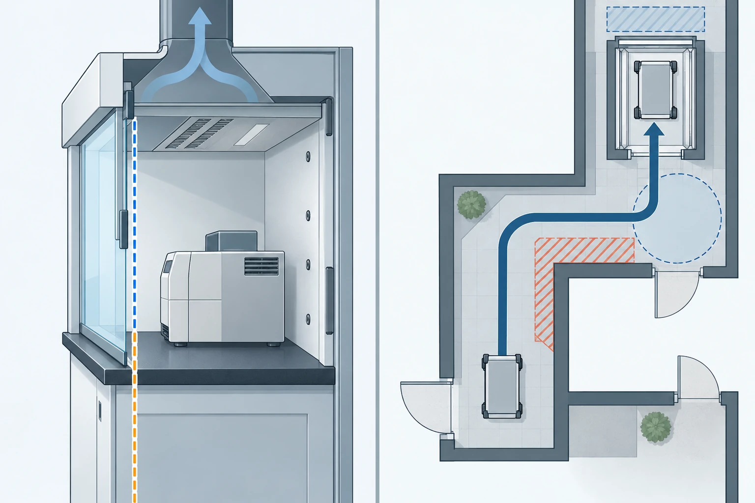
- Corridor Turn Radii: Calculate corner diagonal clearances; a rigid 6 ft or 8 ft cabinet often cannot negotiate a 90-degree turn in a standard 6-foot corridor without colliding with doorway trim.
- Laboratory Entryway: Measure clear door openings between jambs with doors open at 90 degrees; standard single commercial doors often restrict passage.
Where architectural constraints preclude moving an assembled 6 ft or 8 ft cabinet through narrow historic corridors or small service elevators, engineering specifications must mandate sectional delivery. Sectional cabinets ship as modular sub-assemblies designed for mechanical fastening and sealing directly on the laboratory bench. Field seams must be joined using chemical-resistant elastomeric seals or hot-air polypropylene welds to preserve air tightness. In addition, planners must verify service chase penetrations, upper duct stubs, and roof exhaust connections against published laboratory fume hood installation requirements and general fume hood placement requirements.
Rigging teams must also plan for floor loading capacities along transport corridors, utilizing heavy-duty equipment dollies or machinery skates to avoid damaging vinyl flooring. Walking the physical route with a laser measure before issuing purchase orders eliminates costly field installation delays. You can determine whether sectional shipping is mandatory by surveying all building doorways and elevator cabs along the path of travel.
Before releasing the purchase order, the project team should walk the full delivery route with a laser measure and record every limiting doorway, corridor turn and lift so that sectional delivery is priced and scheduled early rather than discovered on installation day.
Sizing Outside the Documented Range: Custom and Oversized Hoods
Standard catalog models spanning 900 mm to 2400 mm satisfy most educational and analytical requirements. However, specialized pilot plant operations, continuous flow synthesis, and automated robotic systems frequently require sizing outside the documented range.
When an enclosure exceeds 8 ft (2400 mm) in span, structural engineering and fluid dynamics shift significantly. Superstructures exceeding 8 ft experience substantial mechanical loading on horizontal lintels and sashes. Vertical rising glass sashes on an 8 ft or 10 ft enclosure become excessively heavy and cumbersome to operate. Consequently, industry standards recommend equipping oversized enclosures with horizontal sliding sashes mounted in multi-track frames. Horizontal sashes allow operators to create localized working access while keeping the remainder of the face opening closed, preserving containment and reducing exhaust airflow. Upper guide rails must be reinforced with precision ball bearings to avoid track binding across wide spans.
Exhaust duct connections also scale with enclosure width. While 1200 mm and 1500 mm cabinets typically use a single round exhaust collar measuring 10 to 12 inches in diameter, enclosures wider than 6 ft require multiple exhaust collars spaced evenly across the roof plenum. Relying on a single exhaust collar on an 8 ft or 10 ft enclosure generates severe lateral pressure gradients, starving the outer corners of face velocity while over-drawing air directly beneath the collar. Multiple exhaust duct stubs ensure balanced capture velocity across the entire width of the baffle system. Across long spans, independent multi-zone rear baffles are necessary to compensate for localized thermal plumes produced by large hotplates or automated synthesis blocks. Adjusting individual baffle leaf positions allows balance testing technicians to fine-tune face velocity across the left, center, and right sectors during initial commissioning.
Engineering custom chemical enclosures requires defining specialized liner materials, such as seam-welded polypropylene or heavy-gauge stainless steel, alongside unique dimensional envelopes. Monolithic polypropylene construction eliminates exposed mechanical joints that deteriorate under severe acid fumes. Planners must provide HVAC engineers with total volumetric exhaust rates and static pressure drop curves for non-standard exhaust plenums. Custom enclosures also require coordination of structural seismic floor anchoring and specialized utility piping drops before construction drawings are released. In addition, third-party containment validation using tracer gas testing protocols should be scheduled immediately following field assembly. Specifying oversized hoods requires detailed mechanical coordination between laboratory architects, equipment vendors, and sheet metal fabricators. You can determine whether a custom enclosure requires multiple exhaust collars by evaluating whether cabinet span exceeds 6 ft.
The Size Fields to Put in Your RFQ and Drawing
Translating dimensional decisions into enforceable procurement contracts requires structured technical specifications. Ambiguous purchase descriptions such as “standard 6 ft fume hood” lead to mismatched worktops, incompatible utility feeds, and field rework.
Architects, engineers, and laboratory procurement specialists must complete a formal checklist of dimensional parameters for every Request for Quote (RFQ) and submittal drawing:
| Specification Field | Required Engineering Metric | Contractual Significance |
|---|---|---|
| Nominal Exterior Width | Inches / Millimeters (e.g., 72 in / 1800 mm) | Establishes overall architectural footprint along casework run |
| Minimum Usable Interior Width | Clear span between side airfoils (e.g., 61.4 in / 1560 mm) | Guarantees required horizontal apparatus clearance |
| Minimum Usable Interior Depth | Worktop surface from baffle to front sill (e.g., 26.8 in / 680 mm) | Ensures compliance with 6-inch front apparatus setback |
| Minimum Usable Interior Height | Vertical clearance from worktop to top liner (e.g., 45.3 in / 1150 mm) | Accommodates tall glassware or vertical equipment stacks |
| Operational Sash Height | Working opening height (e.g., 18 in / 457 mm) | Sets baseline airflow CFM demand for mechanical design |
| Maximum Setup Sash Height | Full loading opening (e.g., 28 in / 711 mm) | Dictates vertical clearance for loading large instruments |
| Worktop Standing Height | Top of counter above finished floor (e.g., 36 in / 915 mm) | Establishes operator ergonomics and base casework alignment |
| Exhaust Collar Dimensions | Diameter and quantity of duct stubs (e.g., 2 × 10 in dia) | Defines mechanical contractor ductwork connection interface |
| Maximum Delivery Dimensions | Width × Depth × Height of largest crated component | Verifies transportability through building doorways and elevators |
Omission of internal clearance minimums is the single most common cause of procurement failure. When submittal drawings arrive from shortlisted manufacturers, project teams must verify that all exterior and interior dimensions, utility service locations, and exhaust collar transitions are fully dimensioned. Verifying these fields protects facility budgets from unexpected field modifications. You can now compile these dimensional metrics into your equipment RFQ before requesting formal manufacturer quotes. Specifying these parameters ensures you select the correct fume hood size for your laboratory.
Conclusion: Systematic Sizing Prevents Costly Facility Rework
Selecting the proper ventilation enclosure requires balancing internal equipment requirements, room space, and facility mechanical capacity. Chemical laboratory planners must avoid the pitfall of treating nominal catalog widths as usable space. Real-world apparatus envelopes require dedicated allowances for side airfoils, rear exhaust baffles, and mandatory front safety setbacks.
A systematic sizing sequence follows four disciplined engineering phases:
- Define the Apparatus Envelope: Measure actual equipment clusters and add required aerodynamic margins.
- Calculate Exhaust Impact: Multiply operational sash opening area by target face velocity to establish HVAC demand.
- Verify Casework and Clearances: Confirm worktop standing height, interior depth, and structural mounting.
- Audit the Delivery Pathway: Survey every doorway, corridor, and elevator along the route from the loading dock.
Executing these verification steps ensures that new enclosures integrate into laboratory workflows without imposing unmanageable ventilation penalties or construction delays. For technical teams seeking factory-engineered solutions, exploring the XICHENG benchtop fume hood portfolio provides detailed dimensional cut sheets for standard and custom polypropylene models. Coordinating these engineering steps ensures your facility specifies the exact fume hood size needed for safe and compliant laboratory operations.
Frequently Asked Questions About Fume Hood Dimensions
Does the width in the model name include the side panels?
Yes, the width listed in standard model nomenclature represents the extreme exterior boundary of the cabinet. Double-wall structural side posts house utility pipes, electrical lines, and aerodynamic airfoils, absorbing between 4 and 10 inches (100 to 240 mm) of total horizontal span. The usable interior fume hood dimensions are always smaller than the nominal cabinet width, requiring review of detailed technical cut sheets.
Is a 4 ft or 6 ft fume hood big enough for my equipment?
Determining whether a 4 ft vs 6 ft fume hood provides adequate space depends on apparatus dimensions and experimental complexity. A 1200 mm (4 ft) unit provides roughly 37.8 inches (960 mm) of internal width, making it suitable for single-instrument setups like rotary evaporators. A 1800 mm (6 ft) unit provides approximately 61.4 inches (1560 mm) of internal width, accommodating multi-flask setups or simultaneous two-chemist operations.
Can a standard fume hood fit through a normal laboratory door?
Standard commercial laboratory doorways often present narrow clearances between open door leaves, while standard fume hood depths range from 750 to 850 mm. While 900 mm and 1200 mm cabinets may clear standard doors when unboxed and carried on edge, deeper cabinets or 6 ft and 8 ft models often exceed corridor turn radii. Facilities with narrow access paths must survey dimensions early and specify sectional modular delivery.
Leave a Reply