

+86 181 2647 8161

Shenzhen Office
COFCO Cloud View Plaza, Hexhuikou Community, Matian Subdistrict, Guangming District, Shenzhen City, Guangdong Province, China
Motorized Air Dampers
Filter by price
Showing the single result
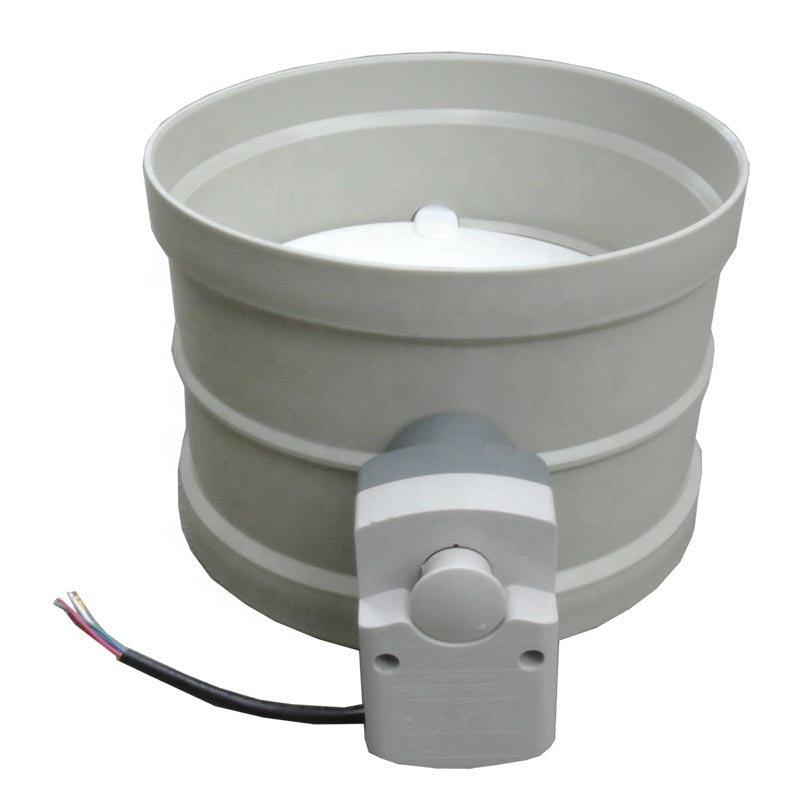
Motorized Air Dampers for Commanded Laboratory Ventilation A motorized air damper combines a duct-mounted airflow-control body with an electric actuator so the blade position can change in response to an operating command. The category currently includes the PP/PVC motorized air volume control damper for compatible laboratory supply and exhaust systems. Final performance depends on the damper, actuator, sensing strategy, controller, duct conditions, and commissioning.
Specify the Damper and Actuator as One Assembly Provide the duct geometry and size, airflow range, available pressure, air-stream chemistry and temperature, body and exposed-part material, connection, mounting orientation, and maintenance access. The actuator schedule should define torque, runtime, power supply, on/off or modulating command, feedback signal, direction of rotation, fail position, communication, enclosure requirements, and how the assembly responds after power or signal loss.
Define How Airflow Will Be Verified Blade position is not the same as measured airflow. Identify the airflow sensor or balancing method, control sequence, minimum and maximum setpoints, alarm behavior, BMS points, and site acceptance criteria. Confirm the required straight duct and measurement locations before fabrication and installation.
For manual balancing with a fixed set position, use Manual Air Dampers. If the project already has a separate valve body and only needs the drive package, review Damper Actuators. This product category does not cover fire, smoke, certified shutoff, or liquid butterfly valves. Submit the duct and controls schedules together for selection.