


Description
Double-Sided Fume Hood for Controlled Opposing-Side Access
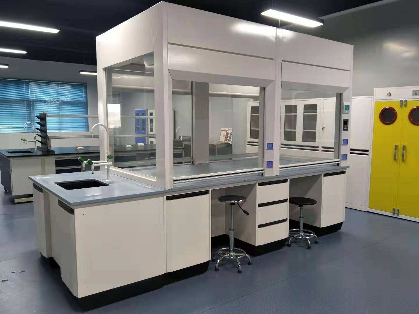
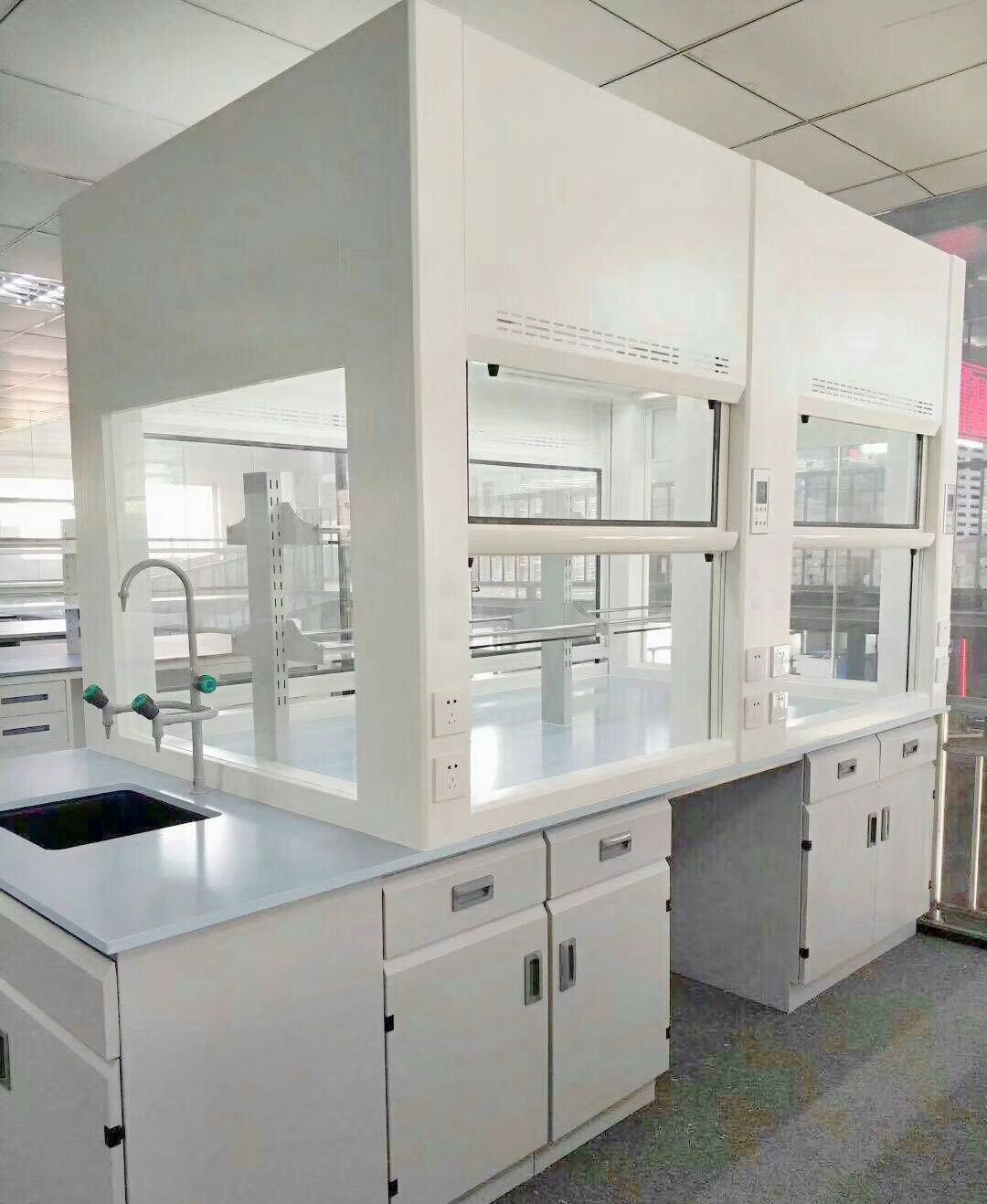
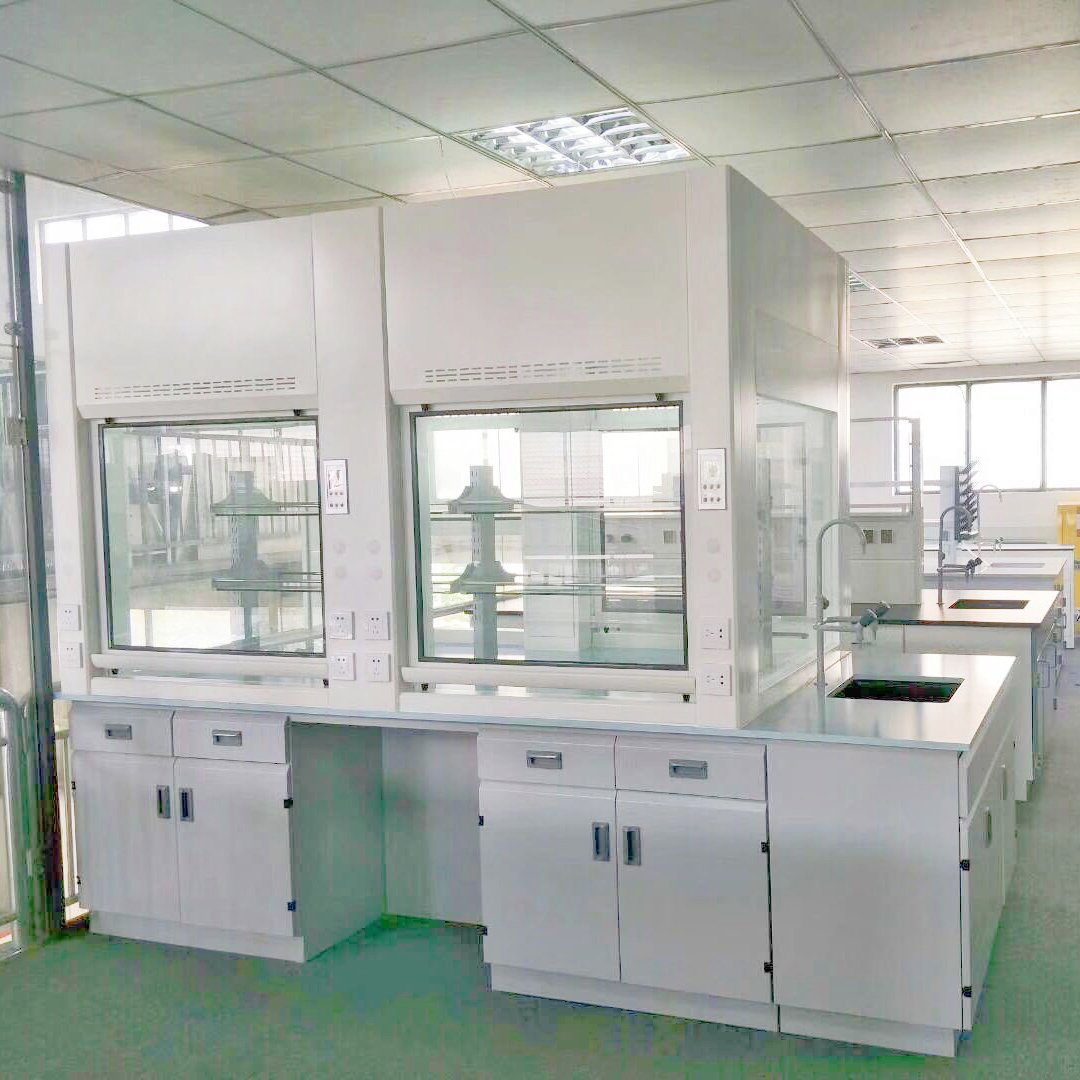
A double sided fume hood is an externally exhausted laboratory enclosure designed with access faces on two opposing sides. It supports teaching demonstrations, supervision, central-island work and selected classroom/preparation-room arrangements where users need visibility or controlled access from either side. The two faces are engineered as one hood with a coordinated work surface, sash system, baffle, exhaust path, services and operating sequence.
The defining requirement is controlled dual entry. A clear rear or end window can improve observation, but glazing alone does not create a second access face. Likewise, placing two conventional hoods back to back does not automatically create one coordinated dual-entry enclosure. The offered product must identify the actual sash faces, permitted openings, air path and exhaust connection.
For normal hazardous work, the baseline selection assumes that the approved working side is open while the opposing sash remains closed. A mechanical or electrical interlock may enforce that sequence. If a project needs another state, including setup access from both sides or a special simultaneous-opening condition, that state requires its own documented airflow, pressure, control and test basis rather than an assumption based on cabinet appearance.
What Defines a True Double-Sided Hood
A true dual-entry design accounts for the geometry and movement of both sash assemblies. Counterweights, guides, stops, sensors, locks and service access must fit without interfering with fixtures or transparent viewing panels. The work surface and sill must serve both entry directions, while the baffle and outlet collect air from the permitted open face without relying on a single-sided cabinet layout.
The installation also affects product identity. On central island casework, both sides may open into one laboratory, with student circulation and supply-air patterns around the complete island. At a classroom/preparation-room boundary, each face opens into a different room. The latter arrangement introduces two room-air and pressure conditions that must be coordinated with the hood branch.
A demonstration fume hood emphasizes clear sightlines for an instructor and observers. An island fume hood emphasizes central placement and access around the enclosure. These commercial terms overlap with dual entry, but they are not identical technical specifications. The project schedule must still state which sides open, which sides are fixed viewing panels, and how operation is controlled.
Multi-sided configurations can add transparent end walls, additional observation faces or another access arrangement. Each face is classified as fixed viewing, service access or operating access. Calling every transparent surface an “open side” would misstate both the double-sided fume hood and the airflow condition.
Product Selection Summary
Select the double-sided fume hood from the required access and teaching sequence, not from a preference for more glass. The decisive inputs are which users work from each side, which sash may open during each task, where observers stand, how the hood connects to the room and exhaust system, and which components are included in the supplied package.
When to Choose a Double-Sided Fume Hood
The dual-entry configuration is appropriate when an instructor must demonstrate from one side while students observe from the other, when supervised work may be performed from either side at different times, or when the hood forms a controlled interface between a classroom and preparation room. It can also support a central island where the project needs clear sightlines and managed access around the enclosure.
The double-sided fume hood is a strong candidate when the process fits a raised work surface, the permitted opening can be defined, and the exhaust system can be selected for that opening. The project should be able to establish an apparatus/load condition, component materials, services, room-air state, control sequence and site-verification method.
A double sided fume hood also requires an ownership plan for the shared work zone. The specification should identify who controls the active side during a class or process, how changeover is authorized, where materials are staged, and how the opposing side is kept clear. In a busy teaching laboratory, these operational details determine whether the second access face improves supervision or creates conflicting user movements.
Teaching visibility is useful only when the layout supports supervision. Sightlines should show the work without placing observers in the operator’s movement path or directly in front of another active sash. Lighting, glare, glazing frames, fixtures and apparatus can all affect what students can see. These details belong in the layout review.
Do Not Select It from Visibility Alone
A fixed transparent rear panel or transparent end walls may be enough when only observation is required. Adding a second operable sash increases the possible opening area, changes the air-entry geometry and introduces another mechanism that must be controlled. If users never need opposite-side access, a single-entry hood with appropriate viewing panels may provide a clearer operating basis.
The double-sided fume hood should not be treated as a shortcut for room-to-room transfer. Passing equipment or materials through the hood can disturb apparatus, expose both rooms and conflict with the working sash sequence. A controlled pass-through use requires explicit loading, decontamination, door/sash-state, pressure and supervision procedures.
It is also not automatically suitable for every educational experiment. Chemical identity, quantity, temperature, energy, aerosol/vapor generation and credible upset conditions still govern enclosure and material selection. Specialized hazards may require a purpose-built hood rather than a general double-sided teaching enclosure.
Central Island or Classroom/Preparation-Room Layout
A central-island hood opens into one room, but it experiences activity and supply-air influence from more directions than a wall hood. Casework, stools, equipment, aisles, doors and student circulation should remain outside the defined working zones. Ceiling service panels and exhaust routing must be coordinated before the island position is fixed.
Island utilities may rise from the floor, descend from the ceiling or enter through coordinated casework. Plumbing, electrical and data points must not block sash guides, counterweights, access panels or observation paths. The base arrangement should state which cabinets, knee spaces, sinks, storage units or structural supports are included.
A classroom/preparation-room installation forms a boundary between two spaces. The hood is affected by the supply and exhaust conditions on each side, door operation and the pressure relationship between rooms. The operating sequence should state which side is normally used, whether transfer is permitted, and how the opposing sash remains secured while work is active.
The room-boundary decision should be made before architectural finishes and mechanical services are released. The wall thickness, structural opening, work-surface continuity, counterweight access, controls, fixture handles and maintenance panels can require space on both sides. Early coordination prevents a finished classroom wall from blocking the mechanism or forcing critical service components into the preparation-room circulation path.
Central-island and wall-boundary arrangements also create different future-change risks. Moving an island supply diffuser, adding stools or converting a preparation room to another pressure regime can change the approved operating environment. The quotation and handover package should identify the room assumptions that must be preserved or reviewed.
Maintenance access also differs. A mechanism or service panel placed in the wall zone may be difficult to reach after surrounding construction is complete. The architectural opening, removable panels, counterweight paths, duct connection and utility isolation should be shown together on the approved installation drawing.
Key Specifications, Sash States and Exhaust Fields
A double-sided laboratory hood specification must describe the complete offered configuration and every permitted access state. Width alone cannot show whether the hood supports the intended teaching sequence or exhaust condition. The double-sided fume hood drawing, sash schedule, material schedule and airflow/control basis should therefore use the same revision and configuration identifier.
Project-Confirmed Product Specification
| Specification Field | Selection Basis | Approved Deliverable |
|---|---|---|
| Installation type | Central island, free-standing, or classroom/preparation-room boundary | Plan, elevation and architectural/interface details |
| External dimensions | Room footprint, ceiling, aisles, wall opening, delivery and adjacent casework | Overall width, depth and height |
| Clear internal envelope | Apparatus, teaching sightlines, sash frames, baffle and fixtures | Usable width, depth and height with obstructions shown |
| Work surface and base | Process load, spill needs, services, island casework and accessibility | Material, elevation, support, penetrations and included base scope |
| Opposing sash system | Operating, observation, loading, pass-through and maintenance sequence | Sash type, travel, opening limits, interlock and fail behavior |
| Viewing panels | Instructor/student sightlines, glare, impact and process exposure | Fixed/operable face classification, glazing and frame schedule |
| Process-facing materials | Chemical, vapor, splash, temperature and cleaning exposure | Liner, baffle, work surface, sill, glazing and exposed components |
| Services and lighting | Required media, electrical load, controls and access from each side | Fixture type/location, isolation, lighting and field connection |
| Exhaust connection | Dual-face air distribution, duct route, flow and hood pressure | Outlet quantity, size, location, material and connection boundary |
| Controls and verification | CAV/VAV, sash inputs, interlock, alarms, BMS and acceptance method | Device scope, point list, sequence, setpoints and test plan |
Each line should contain a selected value, an explicit construction statement or an identified pending decision. Phrases such as “standard double-sided size,” “safe interlock” or “suitable exhaust” are not approval data because they do not identify the geometry, mechanism, opening or system condition.
External and Internal Geometry
External geometry is coordinated with the room and casework. A central-island hood needs clear circulation and service access around the complete footprint. A wall-boundary hood needs a coordinated opening, wall thickness/finish, access panels and interfaces in both rooms. Ceiling enclosure, duct connection and utility routes are shown in relation to the finished building.
The clear internal envelope is measured after accounting for both sash frames, airfoils or sills, baffle projection, lighting enclosure, fixtures and end posts. A nominal exterior depth can overstate usable work-surface depth. The drawing should identify the apparatus zone and preserve the air passages needed for the approved open face.
Dimensions also govern sightlines. The work-surface elevation, sash rails, baffle and apparatus should not block the intended view between instructor and observers. Sightline review is performed from realistic standing or seated positions and includes glare and reflection; it is not inferred from the percentage of transparent area.
Published products commonly offer several reference widths, but those market series do not define the XICHENG product. Final width, depth, height, work-surface elevation and clear openings are set by the project drawing. This preserves useful customization without publishing a false fixed model schedule.
Opposing Sash and Opening Schedule
The opening schedule is the central technical record for the dual-entry enclosure. It lists which side may open, to what position, for which task and under which exhaust/control state. A mechanical stop, lock, sensor or controller should correspond to the named states rather than being described without an operating purpose.
| Operating State | Side A Sash | Side B Sash | Exhaust / Control Basis | Required Evidence |
|---|---|---|---|---|
| Normal work from Side A | At marked working opening | Closed and secured/interlocked | Scheduled flow and hood pressure for Side A opening | Balance, alarm and applicable hood test |
| Normal work from Side B | Closed and secured/interlocked | At marked working opening | Scheduled flow and hood pressure for Side B opening | Balance, alarm and applicable hood test |
| Observation-only teaching | Project-defined operating side | Closed or fixed viewing condition | Normal approved operating state | Sightline and operating-procedure check |
| Setup / loading | Project-defined access position | Closed or separately defined access state | Documented fan/control state and process restriction | Access and interlock sequence test |
| Maintenance | Secured for service as required | Secured for service as required | Isolation and maintenance procedure | Lockout/access record |
| Fault / power loss | Side A behavior per approved fail-state design | Side B behavior per approved fail-state design | Alarm, device and fan behavior as scheduled | Functional failure test |
| Installed acceptance | Side A test position where applicable | Side B test position where applicable | Measured flow, pressure and representative room condition | Complete test report |
The default baseline does not include simultaneous full opening. If a project requests any two-side opening state, it must be shown as a separate row with its calculated exhaust demand, available fan/branch authority, room-air consequence, control logic and acceptance method. The request may be rejected if the configuration cannot support a defensible operating basis.
Airflow, Static Pressure and Test Condition
Exhaust volume is related to the approved open area and selected performance basis. Hood static pressure is reported at that flow for the offered baffle and outlet configuration. A flow value without a sash state is incomplete, and a static-pressure value without the matching flow cannot be used to select the fan branch.
Normal Teaching / Process State
The normal state identifies the active side, marked working opening, opposing sash condition, representative apparatus and room mode. The instructor, students and observers occupy their intended positions without crowding the active sash. This repeatable arrangement is used for balance, alarm settings and the specified performance verification.
Opposing Sashes, Visibility and Construction
The two access faces share one enclosure and must be coordinated mechanically, visually and aerodynamically. Sash hardware cannot be selected independently from service fixtures, side glazing, baffle depth or maintenance access. The approved construction drawing should show both faces, the side/end zones and the complete movement and service envelope.
Mechanical and Electrical Sash Interlock
An interlock limits the permitted relationship between opposing sashes. A mechanical arrangement can use linked locks, catches or movement constraints that do not depend on a software command. An electrical arrangement can use position sensors, locks/actuators and control logic. The appropriate type depends on sash mass and travel, operating sequence, override requirements, power availability and the required failure response.
The technical schedule should describe behavior rather than relying on the word “interlocked.” It states what happens when Side A is raised, how Side B is retained, which positions trigger the condition, whether an authorized setup override exists, and how the system is restored. For an electrical system, loss of power, sensor disagreement, broken communication and actuator/lock faults each need a defined result.
Mechanical components must remain accessible for inspection and adjustment. Counterweights, cables/belts, pulleys, guides, stops and locks should not be concealed behind permanent wall finishes. Electrical systems require labelled terminals, point lists, local indication, test provisions and an identified control boundary.
The interlock does not prove containment. It limits an opening combination so the exhaust and test basis remain meaningful. Airflow monitoring, room-air coordination, procedures and site verification remain separate requirements.
Observation, Sightlines and Instructor Supervision
A demonstration fume hood should let observers see the work without standing in the operator’s access zone. Transparent end walls, opposing sash glazing and a clear interior can support a direct line of sight. Frames, service posts, raised sash rails, fixtures and apparatus are reviewed from the actual student and instructor positions.
Observation does not require opening the viewing side. In many teaching sequences, one face remains closed while students view through it and the instructor works from the active side. This preserves the scheduled opening and separates observer circulation from the operator’s movement. If students later use the opposite face, that becomes a separate controlled operating state.
Lighting should illuminate the work surface without producing glare that hides the demonstration. The light enclosure remains outside or isolated from the process chamber according to the selected construction, and maintenance access does not require uncontrolled sash opening. Camera or display systems may supplement direct viewing when class size or accessibility prevents a clear line of sight.
Supervision also depends on communication and emergency access. The instructor needs to observe users, reach isolation controls and direct evacuation without crossing the active sash plane. The room plan should show observer zones, instructor positions, aisles and nearby safety equipment rather than treating visibility as a cabinet-only feature.
Work Surface, Liner, Baffle and Glazing
The work surface is selected for the process load, chemical/thermal exposure, spill detail and service penetrations. An island arrangement may integrate the hood with wider surrounding casework, but the approved drawing distinguishes the hood work zone from sinks, storage and general bench areas. Base cabinets are listed separately, especially where specialized storage rules apply.
The liner and baffle face the conveyed air stream and process exposure. A dual-entry baffle arrangement must draw from the approved open face while avoiding an uncontrolled short path from the closed opposing side. The final geometry, slots/openings and exhaust outlet are engineered for the offered width and operating condition; no generic single-face baffle dimension is imported.
Glazing is selected for safety, visibility and documented exposure. Fixed viewing panels, operable sashes and service-access panels have different functions. The schedule identifies each panel and frame material, movement/retention method and replacement access. Clear material is not described as universally resistant to every solvent, acid, heat source or impact.
Airflow, Exhaust and Control Integration
The exhaust system is selected for the actual double-sided enclosure and its permitted opening states. A conventional single-entry airflow value cannot be transferred without checking open area, baffle/outlet geometry, room conditions and the opposing sash. Every airflow and hood static-pressure entry in the schedule must name the active side and test condition.
Air Path with One Opposing Sash Open
In the normal baseline, room air enters through one marked working opening, passes across the work zone and reaches the baffle/exhaust path while the opposing sash remains closed. The closed face is part of the enclosure boundary, even though it provides visibility. Gaps, bypass openings and other intentional air paths are included in the hood design rather than treated as accidental leakage.
Apparatus, service hoses, instructor hands and demonstration materials can obstruct or redirect the entry path. Their representative positions should be included in the project review and acceptance setup. An empty hood may be useful for initial balance, but it does not reproduce a teaching demonstration with equipment near the center of the shared work surface.
The active side can change between sessions. Side A and Side B may see different supply diffusers, doors, observer traffic or room pressures, so the commissioning plan checks both permitted directions. Symmetrical cabinet appearance does not guarantee identical installed air conditions.
A two-side opening, where specifically requested, creates a different condition rather than a larger version of the normal state. Air can enter from both faces and interact across the chamber. The resulting exhaust demand, baffle distribution and room-air impact require configuration-specific engineering and testing.
CAV/VAV, Airflow Monitor and Sash Inputs
A CAV arrangement maintains the scheduled branch quantity for a defined opening state. The interlock and sash stops help keep operation within that state. Opening a sash beyond the marked limit changes the open-area relationship even if fan flow remains constant, so a high-sash alarm or procedure may still be required.
A VAV arrangement can adjust branch flow according to selected inputs such as active sash position and measured airflow or face-velocity feedback. The controller must know which side is active and how conflicting or invalid sash signals are handled. Minimum, normal and maximum states are coordinated with the fan and room-air system.
The local airflow monitor identifies the measured or inferred variable, units, normal range, thresholds, delays and reset behavior. Interlock status, sash status and airflow status should remain distinguishable. A “locked” indication is not an airflow measurement, while a normal airflow indication does not prove that the opposing sash is secured.
Remote integration can include active-side status, sash positions, interlock/fault state, airflow alarm, branch command/feedback, fan status and emergency command. The point list identifies signal type or protocol, source of truth, update behavior and responsibility for commissioning.
| System State | Sash / Room Input | Required Response | Verification | Record |
|---|---|---|---|---|
| Side A normal | Side A working opening; Side B secured; representative room mode | Maintain scheduled exhaust and applicable room relationship | Flow/pressure, alarm and specified hood test | Side A baseline |
| Side B normal | Side B working opening; Side A secured; representative room mode | Maintain scheduled exhaust and applicable room relationship | Flow/pressure, alarm and specified hood test | Side B baseline |
| Sash changeover | Approved closing/opening sequence between faces | Prevent conflicting opening and coordinate flow demand | Functional transition test | Sequence timing/settings |
| High or invalid opening | Sash beyond limit or conflicting position inputs | Alarm and apply the approved interlock/control response | Simulated position test | Threshold and result |
| Low airflow / fan fault | Measured condition or fan status outside approved state | Local/remote alarm and documented operating response | Controlled fault test | Alarm setpoint/delay |
| Power / communication fault | Loss of interlock power, sensor, controller or network | Execute named sash, branch and alarm fail behavior | Loss-of-signal test | Fail-state result |
| Emergency mode | Local or building emergency command | Execute approved hood, exhaust and room-air sequence | Integrated systems test | Emergency baseline |
Teaching Applications, Layouts and Product Selection
The double-sided fume hood is selected when dual-side access or observation solves a defined teaching, supervision or room-layout need. A double-sided cabinet consumes additional sash, mechanism, service and exhaust-design effort, so the project should identify the benefit before configuration begins. Clear application ownership also prevents the hood from becoming an uncontrolled shared opening.
The double sided fume hood should therefore be specified around a repeatable lesson, process or service task. That task establishes the active side, viewing side, apparatus position, observer zone, service controls and exhaust condition. When several tasks differ materially, each one should appear in the opening and operating schedule instead of being compressed into one generic “teaching mode.”
Classroom Demonstration and Supervised Work
For instructor demonstrations, one operating side can face the instructor while students observe through the closed opposing sash and transparent end panels. This arrangement supports a clear line of sight without adding another active opening. The room plan should show student positions, instructor movement, emergency egress and nearby safety equipment.
In supervised practical work, different groups may use opposite sides at different times. The operating procedure defines changeover: close and secure the first sash, confirm the next side, verify airflow/control status, then begin work. The work surface and apparatus layout should remain suitable from both access directions, or the approved use should identify one primary side.
The hood does not make an experiment suitable merely because it is used for teaching. Chemical quantity, temperature, vapor/aerosol generation, energy and upset conditions still require review. Educational visibility and supervision are added use-case requirements, not substitutes for hazard-specific enclosure selection.
Accessibility may affect work-surface elevation, knee space, controls, reach and sightlines. Where one side uses an accessible configuration, the opposing side and sash mechanism must remain coordinated. The project identifies which positions are intended for operators and which are observation-only.
Central-Island and Controlled Pass-Through Use
An island fume hood can anchor a teaching laboratory by providing sightlines and alternating access around a central work zone. It requires coordinated casework, ceiling/exhaust routing, utilities, circulation and maintenance clearance. General bench space, sinks or storage attached to the island should not obscure the hood’s defined operating zones.
A wall-boundary arrangement allows the instructor or preparation staff to work from one room while students observe from the other. It can also support controlled loading from the preparation side. The architectural opening, wall finish, counterweight/service access and two room-air conditions are developed together.
Pass-through use requires more than an opening on each side. The procedure identifies which materials may be transferred, whether the process must stop, how contaminated items are handled, and which sash remains closed at each step. The hood should not be used as general room-to-room circulation or as an uncontrolled transfer hatch.
Multi-sided viewing can be added through fixed transparent panels without creating more operating faces. Where the project requests a third access face, the double-sided fume hood becomes a different opening/airflow configuration within the family and requires its own engineering and test basis.
Conditions Requiring Another Hood Type
A conventional benchtop fume hood or general-purpose hood may be more appropriate when one operating face is sufficient. Fixed transparent panels can provide observation without the complexity of another sash and interlock. This option should be considered when the second side adds no recurring access value.
A walk-in fume hood is evaluated when equipment stands on the floor, rolls into the enclosure or needs floor-level service. A distillation fume hood is evaluated when tall apparatus needs a low or raised work surface and high internal clearance. The double-sided fume hood remains centered on opposing access and teaching or island layouts.
Processes involving perchloric acid, radioisotopes, high-temperature digestion, flammable-vapor hazardous locations or another specialized risk can require a purpose-specific enclosure. The transparent/dual-entry arrangement does not replace wash-down, contamination-control, heat/corrosion, electrical-classification or other project requirements.
A filtered ductless teaching enclosure should be evaluated independently against the complete chemical inventory, filter capacity, monitoring and recirculation limits. The double-sided fume hood is externally ducted; it does not treat or neutralize contaminants unless a separately engineered treatment system is included.
Configuration and Project-Ready Quotation
Installation, Commissioning and Change Control
The installed hood operates as part of the room, exhaust system and teaching procedure. Delivery and cabinet inspection alone cannot verify a dual-entry configuration. Installation records must connect the approved product drawing to the actual island or wall boundary, both sash faces, services, exhaust branch, controls and permitted operating states.
Island and Wall-Boundary Installation
For a central-island installation, the delivery survey checks the complete hood/casework footprint, aisles, doors, lifts, floor loading, ceiling height and assembly area. Shipment dimensions may differ from the installed assembly. The lifting and erection plan protects sash glazing, frames, work surfaces and mechanisms while keeping service panels accessible.
The island position is set from architectural and mechanical coordinates. Base cabinets or support frames are levelled and anchored, the work surface is installed, and the superstructure is aligned before duct and service connections are finalized. Ceiling enclosure and vertical duct alignment should not pull the hood out of square.
A classroom/preparation-room installation requires coordinated work on both sides of the wall. The opening dimensions, wall finish, structural support, fire/smoke/acoustic requirements where applicable, access panels and service zones are resolved by the project team. Permanent construction must not cover counterweights, interlock components or removable panels.
After assembly, external dimensions, clear internal envelope, work-surface elevation, end/side glazing and both sash travels are checked against the approved drawing. The active/observation sides and room names are labelled consistently across the double-sided fume hood, control and mechanical documents.
Duct, Fan, Room Air and Control Commissioning
The exhaust branch is inspected for material, size, supports, joints, transitions, air valve/damper where applicable and access. Outlet position and connection match the approved hood. The fan and treatment/discharge system, where present, are checked against the full calculated system duty rather than the hood pressure alone.
Air balancing begins after room supply and exhaust systems are available in representative modes. Side A is checked at its marked working opening with Side B secured, then Side B is checked with Side A secured. The report records branch flow, hood/branch pressure, room conditions and active equipment/people setup for each direction.
In a two-room arrangement, both classroom and preparation-room supply/exhaust conditions and door states are recorded. The commissioning team verifies that switching the active side does not create an unreviewed pressure or control condition. Central-island hoods are checked with nearby diffusers, doors and typical circulation considered.
CAV or VAV controls, airflow monitor, sash/interlock inputs, alarms, fan status and BMS points are tested through the approved sequence. Display defaults are replaced by commissioned values. Conflicting sash signals, low flow, device fault, power loss, communication loss and emergency commands are tested where included.
Factory and As-Installed Verification
Factory inspection can verify dimensions, materials, assembly, sash travel, interlock function, lighting, fixtures and control-panel operation included in the order. It cannot reproduce the final duct, fan, room-air distribution or classroom/preparation-room pressure relationship unless an agreed test setup specifically includes them.
As-installed verification uses the exact active side, opposing sash condition, working opening, room mode and representative apparatus/load defined in the test plan. Side A and Side B should not be assumed equivalent simply because the cabinet is symmetrical. Each permitted direction receives its own recorded condition.
Where ASHRAE 110, SEFA guidance or another recognized method is specified, the edition, test type, tracer-gas or other setup, challenge condition and acceptance criterion are named. Demonstration/multi-sided geometry may require additional definition or adaptation. A standards name without the exact setup and result is not sufficient acceptance evidence.
Corrective action can include sash/interlock adjustment, air balancing, control tuning, baffle configuration, room supply changes, diffuser changes or procedure revision. Retesting follows the same documented condition unless the project formally changes the approved basis.
Related Fume Hood Configurations
Related products are compared by access, apparatus support and hazard basis. A different hood type may provide better performance and a simpler operating sequence when opposite-side access is not essential. The following options are not material variants of the same product; each solves a different layout or process problem.
General-Purpose or Benchtop Fume Hood
A benchtop fume hood or conventional single-entry hood is appropriate when work occurs from one side and observation can be provided through fixed glazing. It avoids a second operable sash and opposing-side sequence. Selection still requires process-compatible materials, a defined opening, exhaust duty and site verification.
A single-entry hood can be integrated into teaching casework with transparent end walls, cameras or display systems when the class needs visibility but not dual access. This option should be compared whenever the project’s second-side requirement is observation only.
The comparison should include more than cabinet price. A second operable face adds sash hardware, opening controls, commissioning states and service access, and it can change exhaust and room-air requirements. When fixed glazing meets the teaching objective, the single-entry arrangement may reduce operating complexity. When alternating physical access is necessary, the dual-entry configuration provides a defined mechanism and approval path rather than relying on an improvised rear opening.
Specialized Hazard Fume Hoods
A perchloric acid fume hood, acid digestion fume hood, radioisotope fume hood or explosion-proof fume hood is evaluated when the process requires its specific construction or facility provisions. A teaching layout does not remove wash-down, heat/corrosion, contamination-control or electrical-classification requirements.
Where a specialized process also requires student observation, the specialist hazard basis is established first. Viewing and supervision features can then be evaluated without weakening the required enclosure, exhaust, materials or operating controls.
Frequently Asked Questions
What is a double-sided fume hood?
It is an externally ducted laboratory enclosure with access faces on two opposing sides. The sash systems, work surface, baffle, exhaust path and controls are coordinated as one product. It is commonly used for teaching, demonstration, central-island layouts or classroom/preparation-room arrangements that require controlled access or observation from both sides.
Can both opposing sashes be opened together?
Not under the default operating basis. Normal hazardous work is configured with one approved working side open and the opposing side closed or interlocked. Any simultaneous-opening request requires a separately engineered open-area, exhaust, pressure, room-air, control and test condition. The approved opening schedule defines what is permitted.
What dimensions and layout information are required?
Provide room plans, island or wall opening, ceiling/service zones, aisles, accessibility requirements, work-surface size/elevation, apparatus and loads, sash/opening needs, observer positions and maintenance access. For a wall-boundary installation, include both room layouts, wall construction and room-air conditions.
Can it use CAV or VAV control?
Yes. A CAV arrangement serves a defined opening state, while VAV can coordinate branch demand with selected sash/airflow inputs. The quotation identifies included monitor, controller, sash sensors/interlock, air valve or damper, alarms and BMS points. Both configurations require balancing and verification at the approved active-side conditions.
How is the installed hood verified?
Verification checks geometry, sash/interlock function, utilities, exhaust connection, airflow monitor/controls and each permitted operating direction. The performance report names the active side, opposing sash, working opening, apparatus, room mode, airflow/pressure, method, instruments, criterion and result. Factory checks do not replace final installed-system testing.
Contact the Xicheng Engineering Team Today
Send the teaching/process sequence, active and observation sides, room or island layout, apparatus and load, permitted sash states, interlock/failure requirement, materials, utilities, exhaust-system information, room-air conditions, controls/BMS requirements and test basis. Xicheng will use these inputs to prepare a project-specific double-sided hood configuration, technical schedule, drawing scope and quotation within 24 hours.
Shenzhen Office: No. 34 Zhenxing Road (Shengtaian Heavy Industrial Park B), Loucun, Guangming New Dist, Shenzhen, Guangdong, China
WhatsApp: +86 181 2647 8161
Engineering Mailbox: fanalax34@gmail.com
Submit the teaching-laboratory layout and dual-entry requirements for engineering review.