




Key Takeaways
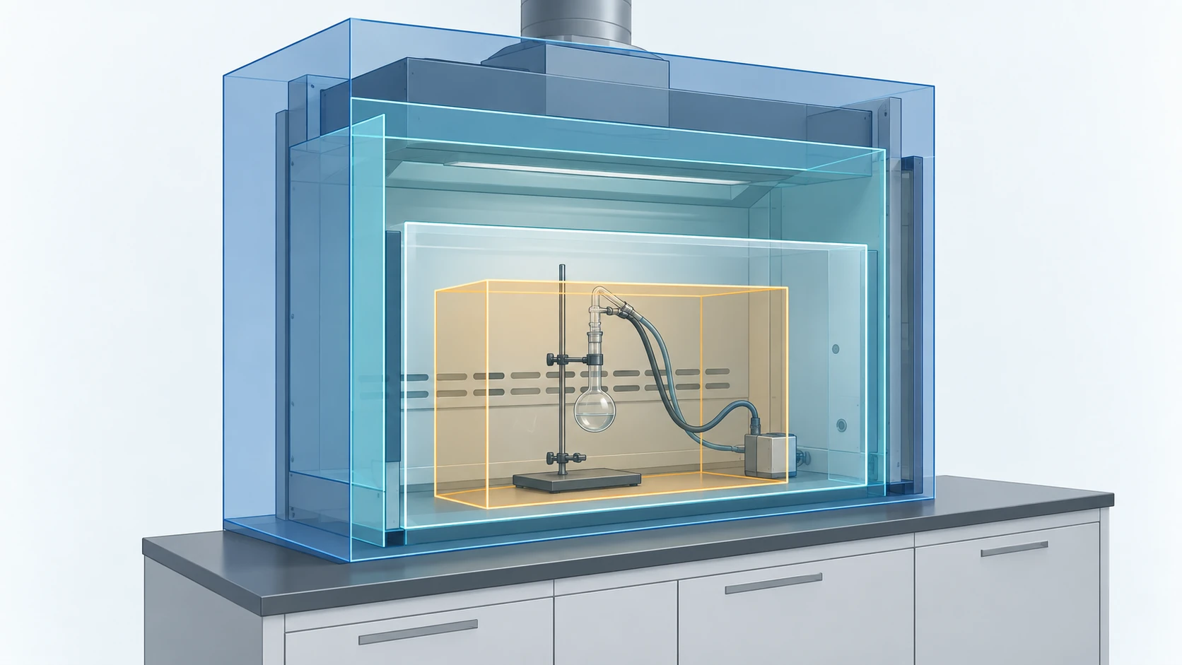
- A fume hood size guide is a method for matching four nested dimensions — cabinet, chamber, clear opening and usable apparatus envelope — to one apparatus. Start from what has to fit, not from a stock width.
- Your apparatus decides the size, not the room and not a stock list. Measure the complete envelope, including hoses, stands and the travel the sash needs.
- The mounting method changes the size you need. A benchtop hood and a floor-mounted hood solve different space problems before any width is chosen.
- A clearance figure without its baseline cannot be checked. Say whether you mean the distance behind the sash plane or from the front edge.
- The delivery route is a dimension. Doors, corridors, lifts, ceiling clearance and turning space can rule out a hood that fits the bench.
Fume Hood Size Guide: The Three Checks That Set Every Dimension
A fume hood size guide answers one question before it answers any other: what has to fit inside the cabinet, and how does the apparatus get there? That question is what decides width, depth, height and the working opening. A stock width does not decide them, and neither does the free wall space in the room.
the direct answer: what a fume hood size guide decides
This guide decides the size of the enclosure from the apparatus you will operate inside it. You measure the complete apparatus envelope first, including hoses, stands, clamps and the sash travel the operator needs, then match that envelope to a chamber, an opening and a route into the building.
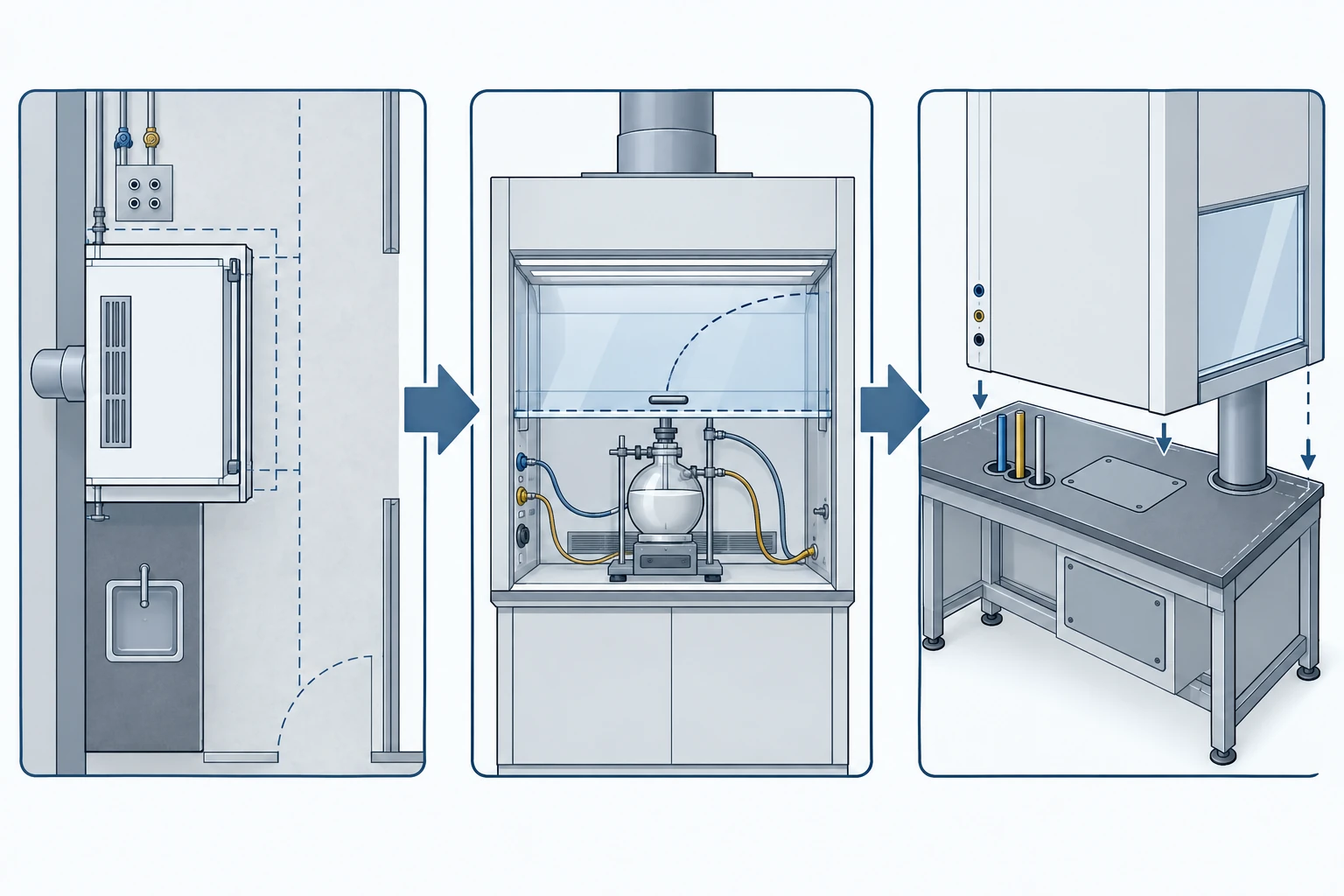
Three checks carry the decision, in this order: the cabinet against the bench, walls, services and access; the chamber against the complete apparatus envelope; the supporting worktop against the load and the service penetrations. Run them in sequence, because each one can send you back to the previous one. A hood that fits the bench but not the corridor is not a valid choice, and a chamber that fits the apparatus but blocks a service panel is not a valid choice either.
Decision landing: you can decide the order of your own sizing work, and you can tell whether your current plan started from the apparatus or from a stock width.
the three checks in order
First check: the cabinet against the bench, the walls, the services and the access route. Compare the overall width and depth with the existing bench, nearby walls, services and aisles — that is the sequence the published sizing method uses. This first check also has to cover the delivery route: doors, corridors, elevators, ceiling clearance, turning space and the final access path into the lab. When the route cannot be cleared, the fix is delivery in sections, an assembly plan or partial disassembly, and the hood’s access panels or sash may have to be removed for handling. Route conflicts are found before the order, not on the day of arrival.
Second check: the chamber against the complete apparatus envelope. The comparison is not against the apparatus body alone. Hoses, stands, clamps, drain lines and the space needed to move the sash all sit inside the same chamber, and the envelope has to leave clearance behind and around the apparatus so air can still reach the baffle and the exhaust path.
Third check: the supporting worktop against load and penetrations. The bench has to accept the selected enclosure without blocking service penetrations or maintenance panels. A hood that fits between two walls can still be unserviceable if the upper connections or the sash mechanism cannot be reached. Confirm this check before the layout is frozen.
The three checks feed one review table: overall size, chamber size, working opening, and the weight and services the bench must carry. Fill the table once, then use it for the quote request.
Decision landing: you can determine which of the three checks your project has already closed and which one is still open, so the next piece of information you collect is the one that can change the size.
what this page does not cover
This page sizes the enclosure. It does not set the sash height rule, the placement distances to walls and adjacent hoods, the face velocity criterion, the fan and duct selection, or the installation and acceptance procedure; each of those is a separate decision with its own inputs. Two boundaries matter here. A walk-in fume hood is a market name for a form of hood, not an occupied work booth, and a person must not enter one while hazardous material is being generated or while a hazardous concentration may remain. And the decision this page replaces is the habit of ordering a bench hood first and adding equipment later.
Decision landing: you can decide what to settle on this page and what to hand to a specialist review, so you stop pulling sash, airflow and placement questions into a sizing decision.
What “Standard” Fume Hood Sizes Actually Measure
Standard fume hood sizes do not exist as one list that fits every lab. Published tables look authoritative and disagree with each other, because they mix sources, units and measurement layers, and a stock list never states which layer it measured. This page treats a nominal width as a market planning increment and every figure as labeled by layer.
what a nominal width includes
A nominal width is the overall width of the hood, measured across the face and the two side panels. It is not the width of the opening you work through. SEFA 1-2010, an industry recommended practice rather than a regulation, states this directly: “A fi ve foot hood includes the width of the face and the side panels and is not a measure of the opening width. Side panels range in width from two to eight inches.” Because side panels vary from 2 to 8 in, two hoods with the same nominal width can have different usable chamber widths, and neither hood is mislabeled.
The width you order is a planning figure; the chamber width is what your apparatus has to fit. Write both into the specification, and neither has to stay ambiguous. That split is why a quotation can be correct and still leave your apparatus short of space.
Decision landing: you can state whether you specified a nominal width or a usable chamber width, and you can decide to ask for the chamber width whenever a nominal width is quoted back to you.
the four layers, defined
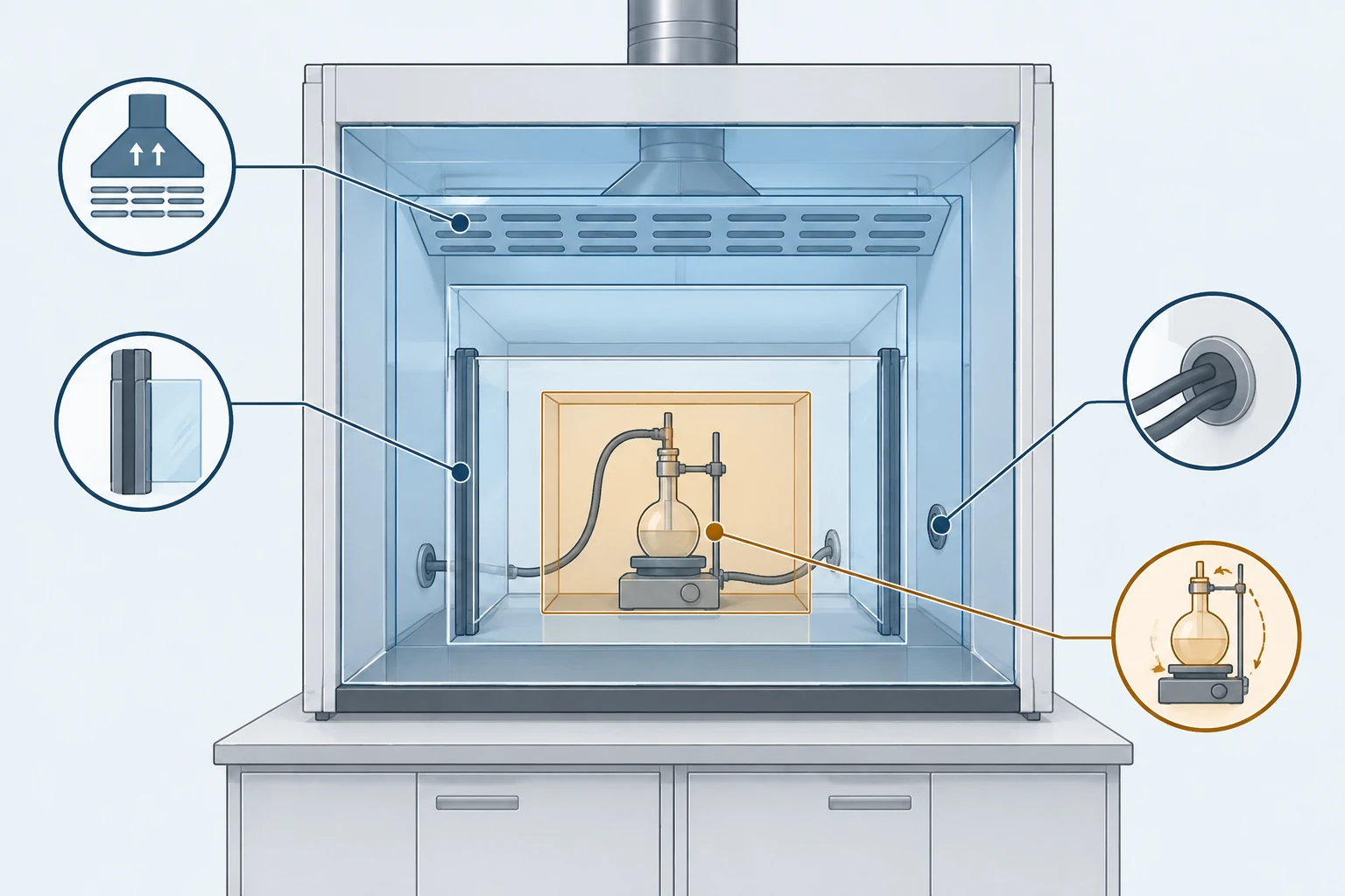
Four dimensions sit between a hood and the equipment inside it: the outside cabinet, the nominal chamber, the clear opening and the usable apparatus envelope. The outside cabinet is the enclosure that reaches the lab and stands on the bench. The nominal chamber is the internal enclosure the maker documents. The clear opening is the gap equipment passes through, measured between the parts that actually limit entry. The usable apparatus envelope is what remains for the apparatus after clearance, services and operating movement. Reductions between those layers are worked through next, from the nominal width down to what an apparatus can occupy.
Exterior size is not a function of width alone. Two documented benchtop configurations from the same manufacturer use 850 mm and 750 mm exterior depths, so one nominal width can arrive at two different overall sizes. Chamber depth and chamber height stay family values rather than width-derived ones, which is why the layer labels decide whether a figure is even comparable.
Decision landing: you can determine which of the four layers each number in your specification refers to, and you can reject a quotation that leaves the layer unnamed.
documented width families versus “standard” sizes
Common thinking runs that 4 ft, 5 ft and 6 ft fume hoods are the standard sizes, so those three widths are enough to plan around. The documented picture is narrower and messier. The NIH Design Requirements Manual lists 1,200–1,800 mm (48–72 in) for vertical-sash benchtop hoods and 1,800 mm (72 in) for horizontal-sash bench hoods, yet that designation governs NIH facilities and binds nobody else. A European manufacturer documents a 4 / 5 / 6 / 8 ft family, and the imperial planning increments run 48, 60, 72, 84 and 96 in. Those families overlap without matching, and no source in this article states one industry-standard width.
The supportable claim is the planning one: a nominal width belongs to a family that a source documents for its own facilities or its own catalog, and the chamber, opening and exhaust values arrive with that family. Confirm the layer of every figure in the table below before it reaches a drawing.
| Family / designation | Nominal width | Exterior size W × D × H | Chamber size W × D × H | Reference exhaust volume |
|---|---|---|---|---|
| Documented benchtop family A | 1,200 mm | 1,200 × 850 × 1,500 mm | 960 × 680 × 1,150 mm | 700–1,300 m³/h |
| Documented benchtop family A | 1,500 mm | 1,500 × 850 × 1,500 mm | 1,260 × 680 × 1,150 mm | 900–1,700 m³/h |
| Documented benchtop family A | 1,800 mm | 1,800 × 850 × 1,500 mm | 1,560 × 680 × 1,150 mm | 1,300–2,100 m³/h |
| Documented benchtop family B | 900 mm | 900 × 750 × 1,400 mm | 868 × 650 × 1,200 mm | Confirm for opening and system |
| Documented benchtop family B | 1,200 mm | 1,200 × 750 × 1,400 mm | 1,168 × 650 × 1,200 mm | Confirm for opening and system |
| NIH vertical-sash bench designation | 1,200–1,800 mm (48–72 in) | not stated by the source | not stated by the source | not stated by the source |
| NIH horizontal-sash bench designation | 1,800 mm (72 in) | not stated by the source | not stated by the source | not stated by the source |
Family values must not be mixed. The manufacturer states that values from one configuration family must not be combined with the chamber or exhaust values of the other, and the table follows that rule: each row stays inside one family, and no cell is filled by interpolation. Family B carries a chamber 30 mm shallower than family A at the same nominal width, and family A documents exhaust ranges where family B says to confirm them for the opening and the system. The interior depth figures make the same point more sharply: a manufacturer elsewhere in the market documents three models at one nominal 4 ft width with chamber depths of 600, 675 and 682 mm, while the two families above differ between 680 mm and 650 mm. No source here states a single industry-standard chamber depth, so a depth figure belongs to the family that published it.
Decision landing: you can decide which documented family your project should follow, and you can flag any specification that presents a width family as a universal standard.
From Nominal Width to Usable Apparatus Envelope
Every enclosure loses space between the cabinet you order and the apparatus you can work with, and the loss happens in a fixed order, never as a margin you can wave away. The chain holds for a benchtop hood and for a floor-mounted hood, and it is the reason a nominal width alone never proves that equipment fits.
The documentation behind this article draws the same line: the outside cabinet, the nominal chamber, the clear access opening and the usable apparatus envelope are four different quantities, and “these dimensions become progressively smaller as sash tracks, baffles, services, thresholds and operating clearances are added.”
how each layer gets smaller
The outside cabinet is the enclosure as delivered: its width, its depth and its height. The nominal chamber is the internal enclosure the maker documents, and it is already smaller in all three directions, because the structure that makes the hood work occupies part of the cabinet.
The clear opening is smaller again, because equipment can only pass where nothing blocks it. Sash tracks, side posts, frames and the sash itself narrow the passage, and the usable opening is measured between the parts that limit entry rather than between the cabinet sides. The usable apparatus envelope is what survives after that: the space left for the apparatus once clearance, services and operating movement are all accounted for.
Decision landing: you can state which layer your equipment has been checked against, and you can decide to reject a fit check that stops at the nominal chamber.
nominal width to chamber to clear opening
The first step down the chain is measurable on paper. A nominal width of 1,200 mm carries a documented chamber width of 960 mm in one benchtop family and 1,168 mm in the other, and a nominal 1,800 mm carries a 1,560 mm chamber. Those are chamber widths, not opening widths, and what sits between them is the frame, the posts and the tracks.
The same layer logic holds in the other two directions. A documented chamber depth of 680 mm or 650 mm sits behind an exterior depth of 850 mm or 750 mm, and a documented chamber height of 1,150 mm or 1,200 mm sits inside a 1,400 mm or 1,500 mm cabinet. Clear opening and usable envelope are not published figures, so the last two steps are done on your own equipment: measure the limiting parts, then measure the apparatus envelope with hoses, stands and sash travel included.
Decision landing: you can determine how much of a nominal width survives into the chamber and the opening, and you can name the dimension that must be measured on site instead of read from a catalog.
why two 4 ft hoods have different usable widths
Two hoods can carry one nominal width and still differ inside, because interior depth and interior height are family parameters rather than values derived from the width. In one documented case, three models sharing a 4 ft nominal size run to 600, 675 and 682 mm of chamber depth, and the two families in this article differ between 680 mm and 650 mm at the same nominal width. Where a question turns on that difference, both figures are the answer, and the family that published each one is the only fair basis for comparison. Depth is not one number either: exterior depth, chamber depth and worktop depth are three separate quantities, and a drawing that gives one without naming which cannot be checked.
Two more pairs get used as if each were a single quantity, and the four layers separate them. Nominal width is a naming convention for the cabinet, while usable chamber width is what an apparatus has to occupy. The maximum opening a sash can reach is not the operating or design sash opening, which is the opening at which the sash stop limits the sash opening. Reference exhaust volume is a planning figure derived from a chosen opening and a stated face-velocity basis, and it is not a measured airflow in an installed hood.
The table below sets out the four layers, what reduces each one, and where each statement can be traced.
| Layer | What the layer is | Items that reduce it | Traceable sources |
|---|---|---|---|
| Outside cabinet | The cabinet as delivered: overall width, depth and height | Nothing inside the cabinet is available for equipment yet; this layer fixes the envelope that has to fit the room, the bench and the route in | Documented benchtop and floor-mounted families; delivery-route conditions |
| Nominal chamber | The internal enclosure the maker documents | Baffles and the exhaust path take interior height; liners, worktop thickness and the rear plenum take interior depth and width | Documented benchtop families; floor-mounted and walk-in chamber values |
| Clear opening | The passage equipment has to move through | Sash tracks, side posts, sash frames, handles, threshold and any temporary lifting or restraint hardware | Documented clear-loading-opening definition |
| Usable apparatus envelope | What remains for the apparatus in service | Clearance behind and around the apparatus so air reaches the baffle, space for hoses, cables, drain lines and valves, and the operating travel of moving parts | Documented usable-envelope definition |
Decision landing: you can choose the layer your apparatus has to satisfy and the family it is checked against, and you can flag any comparison that mixes a nominal width from one family with a chamber value from another.
Fume Hood Size Guide for Airflow: Width, Working Opening and Reference Exhaust
This stage of the fume hood size guide turns a size into an airflow figure, and it needs three inputs that people routinely collapse into one. The cabinet width sets the width of the opening. The sash position sets the height of the opening. The air criterion sets the velocity you intend to hold across it. Airflow follows from those three, so a width on its own predicts nothing.
The published figures that come with a hood are a reference exhaust range, and that range belongs to the planning stage of the project. It is the range for early fan and duct discussions, not a value an installed hood is guaranteed to deliver.
from cabinet width to the working opening
The working opening is the area the air crosses, and the cabinet width supplies only one of its two dimensions. Width and height multiply, so a hood specified at a given width can run a shallow opening or a deep one, and the airflow needed to hold the same velocity changes in direct proportion. Exhaust volume cannot be selected from the maximum cabinet width while the actual open area is ignored. A wider cabinet also does not need more air at the same opening height: the open area drives the volume, not the nominal width.
Two opening conditions then have to be named separately. Setup may need a large opening to load the apparatus, while the process runs at a smaller defined opening. A schedule that records only one of them leaves the airflow figure undefined, because the opening it refers to is unknown.
Decision landing: you can state the opening area you sized for, and you can reject an airflow figure that does not say which opening it belongs to.
design target, field reading and acceptance test
Three values look alike and carry different weight. The design target is what the specification fixes: a width, a working opening and a target airflow, and the fan, the duct and the controls get sized against those. The field reading is what an instrument shows on the installed hood after balancing, and it moves with room conditions, filter loading and control behavior. The acceptance requirement is the condition the project agreed to judge the installation against, and it is written before the test, not after it.
Keeping the three apart changes what a number proves. The operating condition a schedule has to identify covers hood width, working opening, target airflow criterion, exhaust volume and static pressure at the connection. A figure missing any of those cannot be verified or repeated.
Decision landing: you can name which of the three values a given number is, and you can decide what the specification must state before airflow can be checked at all.
the reference exhaust range is a planning input, not a guarantee
A reference exhaust range is a planning figure, and it is not proof of installed containment. That split is documented directly: a reference exhaust range is an early design input, not proof of installed containment, because the final volume depends on the usable sash opening, the intended face-velocity criterion, chamber geometry, baffle arrangement, duct resistance, room air movement and control strategy. Read a range as the band your early fan and duct discussions should aim at, then confirm the opening it was written for.
The same boundary runs between the cabinet and the rest of the system. Cabinet width governs the open area, and the rest follows from system design. The exhaust fan, the ductwork, the controls and the makeup air are sized from required volume, pressure and control strategy, and those responsibilities must be coordinated rather than inferred from the cabinet width. The published method says the same in one line: record both the selected width and the required operating opening before the fan or the control package is sized. So this page stops at the airflow figure and hands the rest onward: exhaust fan sizing and duct sizing carry the fan and duct work, and makeup air and pressure balance and installation and acceptance carry the rest.
Decision landing: you can decide which numbers are yours to set and which belong to the system designer, and you can hand over a width and an opening rather than a wish.
the arithmetic from opening area to exhaust volume
The arithmetic is short, and every input is a number you already hold. Multiply opening width by opening height to get the open area in square meters. Multiply that area by the face velocity you intend to hold, in meters per second, to get cubic meters per second. Multiply by 3,600 to report cubic meters per hour.
The criterion may be stated in feet per minute, so keep the conversion explicit: 100 fpm is 0.508 m/s. That figure sits at the top of the working band in the recommended practice this article cites, which gives a range of average face velocities of 60 to 100 fpm and notes that the measured deviation across the face may vary by 20 fpm. The same recommended practice notes that hoods longer than six feet typically have more than one exhaust collar.
The criterion itself has more than one documented basis, and the sources do not agree on a single figure. Conventional general-purpose hoods are commonly designed for 80–100 fpm, and an alternative path reduces face velocity to 50–60 fpm while holding a generous working opening. The NIH Design Requirements Manual pairs an average face velocity of 0.51 m/s (100 fpm) with a sash design position of 457 mm (18 in) as the premise of its own rating, and that requirement applies to NIH facilities rather than to every project.
The operating sash height used as an airflow basis is unsettled in the same way. An 18 in position is the most frequently documented operating height, while a combination-sash model is rated with a 28 in maximum opening and setup positions reach 28–29 in. Two consequences follow for this module. Never quote a single face velocity as the size conclusion, because the velocity is a design choice that travels with hood type and with the project’s own criterion. Always name the sash position the airflow figure assumes, because one volume means different velocities at different openings. Which recommended-practice statement to apply is a project decision, so state the basis you selected and keep the alternatives visible beside it.
Worked example. A benchtop unit is specified at 1,500 mm nominal width in the deeper benchtop family, whose documented chamber is 1,260 mm wide and 680 mm deep, and the process runs with the sash set at a 400 mm operating opening.
- Open area: 1.26 m × 0.40 m = 0.504 m².
- Target criterion: hold 100 fpm, that is 0.508 m/s across the open area.
- Volume: 0.504 m² × 0.508 m/s = 0.256 m³/s.
- Reported per hour: 0.256 m³/s × 3,600 = 922 m³/h.
Every number in those four lines is either a documented family value or an arithmetic result of the line above it, so the chain can be repeated by hand. Comparing the result with what each family documents is where the answer lives:
| Nominal width | Family | Documented chamber width | Documented reference exhaust range | Volume required at a 400 mm opening under the 100 fpm criterion | Reading |
|---|---|---|---|---|---|
| 900 mm | Family B | 868 mm | Not documented for this family; confirm for opening and system | 635 m³/h | The family publishes no range here, so the volume must be confirmed instead of read |
| 1,200 mm | Family A | 960 mm | 700–1,300 m³/h | 702 m³/h | Inside the documented range, near its lower end |
| 1,500 mm | Family A | 1,260 mm | 900–1,700 m³/h | 922 m³/h | Inside the documented range, with room in both directions |
| 1,800 mm | Family A | 1,560 mm | 1,300–2,100 m³/h | 1,141 m³/h | Inside the documented range, near its lower end |
The family column is not decoration. The 900 mm row sits in family B; the other three rows sit in family A, and a value from one must not be combined with the other family’s chamber and exhaust figures. A 900 mm figure therefore cannot be carried into an A-family comparison, and the 635 m³/h result stands only with the B-family chamber width that produced it.
The table answers the question this module started with. A 400 mm opening draws more air in a wider hood, and the requirement still lands inside the documented band for each width that publishes one. The ends of a band are not the same number as the requirement, either: for the 1,500 mm unit, the lower end of 900 m³/h corresponds to about a 390 mm opening at 100 fpm, so an opening deeper than the band was written for needs more air than the band contains. That is the difference between a planning figure and a guarantee, and it is why the opening belongs in the specification next to the volume.
Decision landing: you can run this example on your own apparatus and determine whether your intended opening fits the reference band, so the airflow figure you send for fan sizing is one you can defend.
Depth and Height: Why They Are Not Functions of Width
Width gets the attention, and the two dimensions that sink more projects are depth and height. Both are documented per family rather than derived from width, and both shrink again once the apparatus has to be operated rather than merely stored. This section works through interior depth, interior height and the chamber families that carry more of each.
One value makes the point before any table does. A 2,000 mm reference chamber height is not a 2,000 mm usable equipment height, because the baffle, the exhaust path, the utility connections and the operating clearance come out of it. Nominal chamber height is a documented dimension; usable equipment height is a project result, and the two numbers are never interchangeable.
interior depth is a family parameter
Chamber depth is where nominal width stops predicting anything. One manufacturer documents three models, all at a stated 4 ft, that reach 600, 675 and 682 mm of chamber depth — a spread of 82 mm inside one nominal size. The two documented benchtop families in this article differ from each other too, at 680 mm for family A and 650 mm for family B, a gap of 30 mm at the same nominal width. Neither figure is an industry value: no source here states a single standard chamber depth, so each depth belongs to the family that published it and travels with it.
Depth also arrives in three different quantities that a drawing can confuse. Exterior depth is what occupies the floor or bench footprint, chamber depth is what the apparatus can use, and worktop depth is the surface the apparatus stands on. A figure that names none of the three cannot be checked against a bench, and the exterior depth of a family changes the depth of the enclosure without changing its chamber at all.
Decision landing: you can determine which depth your apparatus is limited by, and you can reject a comparison that puts one family’s chamber depth beside another family’s width.
interior height and the usable apparatus height
Height follows the same rule and adds one more subtraction of its own. Chamber height is a family value: the two benchtop families in this article document 1,150 mm and 1,200 mm, and a manufacturer elsewhere in the market documents 1,230 mm and 1,435 mm for two models at one nominal width. That 205 mm spread within a single nominal size is the clearest statement that interior height is a family and option parameter rather than a width-derived constant.
Above the chamber sits the part that people skip. Once those four are subtracted, the remaining space is the usable apparatus height, and it is smaller than the chamber on every project. Plan the apparatus against the usable height and treat the chamber figure as the ceiling the subtraction starts from.
Decision landing: you can state the usable height you need rather than the chamber height you were quoted, and you can flag a layout that was checked against the chamber figure alone.
floor-mounted and walk-in chamber families
Floor-mounted and walk-in hoods exist because some apparatus will not fit a bench-height chamber, and their documented chamber heights show what they add. Three documented widths carry a 2,000 mm chamber height inside a 2,350 mm overall height: 1,200 mm, 1,500 mm and 1,800 mm nominal, with chamber widths of 960 mm, 1,260 mm and 1,560 mm, chamber depth of 680 mm at every width, and reference exhaust volumes of 700–1,300, 900–1,700 and 1,300–2,100 m³/h respectively.
The extra height stays conditional. A 2,000 mm chamber height does not become 2,000 mm of usable apparatus height, so the baffle, the exhaust path, the utility connections and the working clearance still come out of it. Width changes the chamber, and height stays a family property. When the apparatus needs more in the vertical direction than a benchtop chamber can offer, the next question is whether a different hood form has the chamber to hold it rather than whether a wider benchtop hood will.
One boundary belongs with the form itself. Walk-in is a market name for a hood type. It creates no work booth to occupy, and entry is prohibited while hazardous material is being generated or while a hazardous concentration could still be present.
Decision landing: you can choose between a deeper chamber and a taller chamber before the project reaches a hood-type comparison, and you can flag either question as outside a sizing decision.
what a larger chamber still does not fix
A chamber that is deep enough and tall enough can still fail, because the apparatus has to be used inside it. Equipment that stands tall, carries a condenser or needs head room behind it may fit the chamber and still leave no room to operate or to load it. When the defining constraint is the process rather than the enclosure, a different hood form is the answer and a bigger enclosure is not.
The same limit applies in the other direction. Apparatus that has to be placed on the floor, hoisted into position or kept clear of a bench top needs a form that offers floor access, and no amount of added width on a benchtop unit changes where the apparatus sits. Both cases are sizing conclusions rather than selection comparisons: the enclosure cannot satisfy the constraint, so the constraint has to move the project to a different form with its own documented dimensions.
Two rules keep that conclusion honest. Equipment needs clearance behind and around it so air can still reach the baffle and the exhaust path, and a clearance figure only means something when its measuring baseline is named. Published baselines disagree with each other, and the clearance rules and the delivery route this page expects you to check are worked through in the next section.
The working surface carries one more sizing decision, and it belongs with the mounting method rather than with the chamber, because documented heights arrive as manufacturer ranges rather than as one accepted value.
Decision landing: you can decide whether your constraint is the enclosure or the procedure, and you can send a form question to the right decision instead of adding width to a hood that cannot solve it.
How the Mounting Method Changes the Size You Need
The mounting method is a sizing input, not a label on a catalog page. A benchtop hood, a floor-mounted hood and a walk-in hood each move the load, the access and the opening to a different part of the room, so one apparatus can require different dimensions in each case. This section covers what changes in the geometry. The comparison rules for choosing between forms stay with their own decision.
benchtop and the worktop interface
A benchtop unit hands three of its dimensions to the bench underneath it. The worktop has to accept the enclosure without obstructing service penetrations or maintenance panels, and it has to carry the load the enclosure and its contents place on it. An enclosure squeezed in with no room at the top can still be impossible to service if the upper connections cannot be reached, so the bench side of the interface is a size constraint rather than a plumbing detail.
The worktop also fixes the working height, and the working height is not one fixed number: it follows the unit and how the enclosure is set up. One adjustable work surface moves between 30 in and 36 in to suit different users, procedures and equipment, and a base stand is offered that supports a 4 ft hood to an accessibility standard for height and knee clearance. Both are options a project selects rather than values a size check can assume, and the second carries a requirement that no chamber dimension can satisfy later.
Decision landing: you can state the load, the service openings and the working height the bench must provide, and you can reject a benchtop layout that was checked against the hood alone.
floor-mounted and walk-in
Floor mounting changes which surface carries the enclosure and which edge the apparatus crosses. The enclosure stands on the floor, so the load lands there instead of on a bench, and equipment moves in at floor level rather than being lifted over a worktop edge. The threshold at the base and the height of the working surface both become dimensions the apparatus has to clear, and the chamber that results is taller than a benchtop chamber because the whole enclosure sits lower in the room.
The taller chamber is where the earlier chamber work pays off. A chamber that stands 2,000 mm high inside a cabinet 2,350 mm tall still loses baffle, exhaust path, utility and operating space before anything can be placed, and the walk-in form carries a safety boundary of its own. Both points are set out with the chamber families above and do not need repeating here. What the mounting method changes is the installation geometry and the opening, not the size of a benchtop hood.
Decision landing: you can determine what the floor and the access edge have to provide, and you can flag a layout that assumes a benchtop footprint under a floor-mounted enclosure.
the sash travel and access opening question
The opening is the dimension that changes most when the mounting method changes. A benchtop hood restricts access to a sash plane above the worktop, while a floor-mounted or walk-in form has to provide a clear opening that equipment can pass through at floor level, measured between the parts that limit entry. One apparatus can therefore satisfy one form’s chamber and fail another form’s opening, which is why the opening belongs in the specification next to the chamber.
Two smaller dimensions travel with the opening. The sash movement needs room of its own, and equipment carried in on a cart or skid needs a wheel path and turning radius inside the enclosure. Where a large setup opening is required, the schedule has to say whether the opening is a loading position or a working position, because the two are not interchangeable. Installation and acceptance as such sit with installation and acceptance, and the form comparison itself sits with benchtop versus floor-mounted selection.
Decision landing: you can choose the access opening each candidate form has to provide, and you can flag a comparison that used one form’s chamber against another form’s opening.
Clearance Baselines and the Delivery Route
Two constraints decide whether a hood that fits the bench can be used and delivered, and both are routinely written as a single number without the detail that makes it mean anything. Clearance inside the chamber is measured from one of two baselines, and the route into the building is a chain of openings rather than a width.
The principles behind both are already in place: the apparatus needs clearance so air can reach the baffle, and the route conditions belong in the first sizing check. What follows carries the numbers and the walk-through.
two clearance baselines: sash plane and front edge
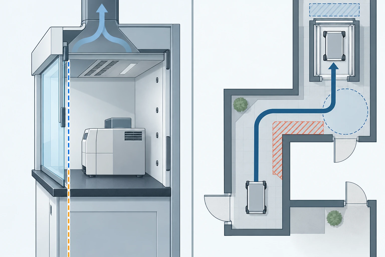
Published clearance guidance uses two different baselines, and the difference is not cosmetic. One institution states that work should be carried on at least 6 inches inside the hood behind the plane of the sash, a practice it attributes to industry standards. The measurement starts at the sash plane, so a 6 in figure describes how far the work sits behind that plane and says nothing about the front edge of the work surface.
Other guidance measures from the front edge instead, placing apparatus 5–10 cm back from the front of the work surface and raising large equipment by 2–3 in. Those figures use the front edge as their zero point, so they cannot be compared with the sash-plane figure directly and cannot be added to it either. Two rules follow for anything that reaches a specification: write the baseline next to the number, and never state a single setback as if every source agreed on one. What no source in this article states is a limit on how much of the work surface equipment may occupy, so no percentage belongs in a clearance rule.
Decision landing: you can state the baseline your clearance figure is measured from, and you can reject a clearance rule that arrives without its reference point.
doors, lifts and the delivery route
The delivery route is a chain of clearances, and the hood fails if any single link fails. The conditions a route has to satisfy are documented as doors, vertical transport, overhead space, the room to swing a long enclosure round and the last stretch to its position, and they belong to the size decision rather than to the shipping desk. The same documentation asks for the door and lift clearances, the unpacking area and any need to remove the sash or access panels for handling.
Turning space matters more than straight width, because an enclosure that passes a doorway lengthwise can still be unable to turn the corner on the far side. Where the route cannot be cleared as delivered, the documented options are delivery in sections, an assembly plan agreed in advance, or partial disassembly to move the hood through. The route also interacts with the chamber, because equipment brought in on a cart or a skid has to be moved, steered and set down after it clears the opening.
No source in this article gives a door width or a corridor width, so none appears here. Route conditions are verified by walking them, and the outcome is a decision about delivery method rather than a value to quote.
Decision landing: you can determine which link of the route is the limiting one, and you can decide the delivery method before the order rather than when the truck arrives.
what the project must confirm instead of a number
Where the evidence stops, the project has to answer instead of copying a figure. Clearance inside the chamber depends on the baseline and on the apparatus, and the route depends on a specific building rather than on a category of building. Both belong on a signed checklist: the baseline chosen, the clearance held, the route conditions verified, the access panels to be removed and the delivery method agreed.
That checklist has a second use. Any number that arrives without a baseline or a route condition attached can be sent back with a specific question rather than refused, which keeps a quotation moving while it stays checkable. The one thing the checklist cannot supply is a number for someone else’s building, and treating it as if it could is how a hood gets ordered twice.
Decision landing: you can decide what the project confirms before the order, and you can flag any clearance or route figure that a supplier has not tied to a baseline.
When the Size You Need Is Outside the Documented Range
Not every apparatus fits inside a documented family, and the useful decision at that point is whether the enclosure or the process is the limiting factor. Enclosure limits respond to a different product. Process limits do not respond to a bigger enclosure at all, and adding width to a hood that cannot satisfy them costs time before it costs money.
The documented rule is blunt about the test. A process should move to a different product when its defining constraint cannot be resolved by changing the width or the liner.
change the hood type, not the width
The test is whether the constraint moves with the width. If a taller chamber would settle the matter, the constraint belongs to the enclosure, and the answer is a hood form that documents the chamber height you need rather than a wider version of the form you started with. If the constraint is how the apparatus is operated or where it has to sit, no width resolves it, and a wider enclosure simply carries the same problem at a higher price.
Both outcomes land outside a width decision: the enclosure cannot satisfy the constraint, so the project moves to a different form with its own documented dimensions.
Decision landing: you can decide whether your constraint travels with the width, and you can stop a specification that is being widened to solve a process problem.
non-standard width, depth or material
A combination that no documented family carries has to go through project configuration rather than through a catalog entry. Nothing here promises that any combination of width, depth, opening, material and exhaust package is available, and the market increments this article has quoted are planning increments rather than a stocked range.
What a project can do is submit the requirement with the information that makes it reviewable: the complete apparatus envelope, the process conditions and the dimensions the layout has to satisfy. A request built that way can be answered on its own terms. A request for a size alone cannot be answered at all, because the constraint behind it is missing.
Decision landing: you can state whether your requirement is a documented family value or a project configuration, and you can assemble the inputs a project review needs before you ask.
what a size outside the documented range still requires
Outside the documented range, the same discipline applies with less margin for error. The four layers still have to be identified, the opening still has to be measured between the parts that limit entry, and the airflow figure still has to name the opening and the criterion behind it. A project configuration changes who confirms the answer, not what has to be confirmed.
That answer arrives through a project review rather than a stock list, and the review needs the apparatus drawing and the process conditions as inputs. Where the volume, the pressure behavior or the control arrangement is part of the question, the airflow work belongs with the system review rather than with the sizing decision that precedes it.
Decision landing: you can flag what still has to be confirmed, and you can name which review produces the answer instead of treating a configuration as a size.
The Size Fields to Put in Your RFQ and Drawing
A size decision only survives the project if it reaches the paperwork, and the paperwork is where most of it leaks. The earlier sections decided the layers, the opening, the airflow basis and the route. This section turns them into the fields a quote request has to carry and a drawing has to state.
One rule governs the whole list. Fields that describe what you intend sit in one group, fields that record what a site actually exposes sit in another, and fields that a test will judge sit in a third. A quote request that merges them cannot be answered precisely, and a drawing that merges them cannot be checked.
the data to gather before you ask for a quote
A quote request needs the apparatus before it needs a preference. The first group is what the apparatus imposes: its complete envelope with hoses, stands and the movement the sash needs, and the load the bench or floor has to carry. The second group is what the process imposes: the opening you intend to work at, the airflow criterion behind that opening, and the static pressure expected at the connection. One documented line names exactly that set: width, opening, airflow criterion, volume and connection pressure.
The third group is the site, and it is measured rather than assumed. Survey the route from the unloading point to the final position, and record the door and elevator openings, corridor widths, turning radii, ramps, floor transitions, ceiling height, overhead services and the load limit of any lifting equipment used. Those figures belong to your building, which is why none appears in this article. Check the route against the shipping sections rather than the finished enclosure, because the packaging can be larger than the hood itself.
Decision landing: you can assemble the apparatus, process and site fields your request needs, and you can send a request that a supplier can answer without guessing which opening you meant.
what the approved drawing has to state
The drawing carries the outcome of every earlier decision, and the fields are all dimensional: the final external and internal dimensions, the worktop interface, the sash travel, the exhaust-collar location, the utility penetrations and the access clearances. Each one answers a question this article raised. External and internal dimensions settle which layer the project bought. The worktop interface settles what the bench owes the enclosure. Sash travel and access clearances settle whether the apparatus can be operated and serviced where it stands. Exhaust-collar location and utility penetrations settle whether the services can reach the hood.
The drawing is also where the three field groups are kept apart, and the test the project will run is the reason. A design target is what the drawing states; a field reading is what an instrument shows after balancing; an acceptance condition is what the project agreed to judge the installation against. Put the target in the specification, leave the reading to the commissioning record and write the acceptance condition down before anyone tests, so a result is compared with an agreed criterion instead of a remembered one. Two review checks keep the drawing honest: the stated width and the required operating opening both appear before fan or control sizing begins, and the responsibilities for support, fixing, sealing and exhaust are coordinated rather than inferred from the cabinet width.
This is the point where a fume hood size guide ends and a specification begins.
Decision landing: you can state what the drawing has to contain, and you can decide which fields your project signs off as targets and which it leaves to a measured record.
Conclusion
The three checks, the four layers and the field groups are one method, and it finishes in a form you can file. Compare the outside cabinet against the bench, the walls, the services and the route in; compare the chamber against the complete apparatus envelope; confirm the worktop against load and penetrations. Name every figure as cabinet, chamber, clear opening or usable envelope before it leaves your desk.
the four layers, restated for the specification
The artifacts are what the project keeps. A check sheet with the three checks and the layer each figure belongs to, a value for the working opening beside the airflow figure it produces, and the field list that the quote request and the drawing both carry. Anything still open at that point is a question for the project rather than a number to estimate.
That last point is the one worth carrying: a fume hood size guide ends where a specification begins, with the remaining unknowns named as questions. Hand those questions over with the sheet, and the answer you get back can be checked against it instead of against a memory.
Decision landing: your next step is to run the three checks with the layer names attached, then send the field list with the open questions marked as open.
Frequently Asked Questions
What size fume hood do I need for my apparatus?
Start from the apparatus, not from a width. Measure the complete envelope with hoses, stands and the room the sash needs to travel, then match it to a chamber, an opening and a route into the building. If a width is quoted back to you without a chamber width attached, ask for the chamber figure before you compare anything.
Are 4 ft, 5 ft and 6 ft “standard” fume hood sizes?
They are planning increments rather than a standard. The widths a manufacturer, a design manual or a catalog documents belong to that source and its own facilities or range, and the market increments overlap without matching. Treat a width as the beginning of a family, and confirm the chamber, the opening and the exhaust values that come with the family you chose.
How much clearance should equipment have inside the hood?
Leave the setback and write down what it is measured from, because two published baselines disagree: one measures from the plane of the sash behind the work, another from the front edge of the work surface. A figure is usable once the baseline sits next to it, and a percentage of the work surface is not a rule you should expect to find.
Decision landing: you can answer all three of these from your own apparatus and building, and you can tell which of them your supplier still has to confirm.
Leave a Reply