




Key Takeaways
- Fume hood duct sizing is a decision about safety, cost and uptime — not a plumbing detail. Work the four steps in order: airflow, transport velocity, diameter, then material and routing.
- Size from the hood’s catalog exhaust airflow plus named allowances, never from the bare face-velocity product or the hood’s connection collar.
- Target 1,000–2,000 FPM transport velocity for gases and vapors (2,500–4,000 FPM for dust), then pick the next standard duct diameter and verify the actual velocity lands inside the band.
- Finish with a duct schedule and a static-pressure handoff to the fan engineer; duct sizing and fan sizing are two halves of one system.
Fume Hood Duct Sizing Is a Safety Decision, Not a Plumbing Detail
When you size a kitchen range-hood duct, the failure mode is noise and a greasy cleanup. When you size a chemical fume hood exhaust duct, the failure modes are corrosion leaks, condensate puddles, fire propagation, and technicians breathing what should have been exhausted. That is why fume hood duct sizing is a decision you should treat as a safety calculation first and a sheet-metal exercise second. This guide walks the four-step path that a lab project actually follows — airflow, transport velocity, diameter, material and routing — and gives you the tables you need to finish a duct schedule in about a week.
Fume hood duct sizing really means four linked choices: the airflow you design for (CFM), the transport velocity you hold inside the duct (FPM), the round or rectangular diameter that delivers that velocity (inches), and the material and routing that survives the chemistry (PP, PVC, CPVC, FRP, 316L stainless, or coated steel). Change any one and the other three respond. A smaller duct at the same airflow raises velocity, resistance and noise; a larger duct at the same airflow drops velocity and lets vapors and condensate settle; a material that is chemically incompatible fails even when the numbers are perfect.
The three ways duct sizing fails
Undersized duct: velocity climbs, pressure loss climbs, the fan cannot move the design airflow, and you hear it in the lab. Oversized duct: at low load, velocity falls below the transport threshold, vapor condenses, dust settles, and corrosion starts at the bottom of the run. Wrong material: the duct corrodes, leaks, or both — and a plastic duct with the wrong fire rating becomes a fire-propagation risk. In every case the failure is discovered after the hoods are installed, which makes it expensive to fix. Good chemical fume hood duct design is the intersection of transport engineering, materials science and fire safety, and the duct is the component that lives inside the building for twenty years.
The counterpart in kitchen hoods — where galvanized steel, low velocity and simple gravity drainage are routine — actively misleads engineers who carry those habits into a laboratory. That is exactly why the first page of results for this topic is full of kitchen content, and why this article takes the laboratory view from the first paragraph. The four steps you need are summarized in Table T1; the detailed modules follow in order.
Table T1 — Four-step duct sizing path
| Step | Decision you make | Key input | Output | Module |
|---|---|---|---|---|
| 1. Airflow | Design exhaust airflow (CFM) | Hood catalog value + allowances | Q for each run | M02 |
| 2. Velocity | Transport velocity (FPM) | Contaminant phase, condensate behavior | V target band | M03 |
| 3. Diameter | Duct size (in / mm) | Q, V, and D = √(4Q / πV) | Standard size + actual velocity check | M04 |
| 4. Material & routing | Material, slope, drains, joints | Chemistry, temperature, fire rating, layout | Duct schedule + checklist | M05–M07 |
What this guide delivers and how to use it
Each step has its own module and its own table. You should work the steps in order on your first pass, then use the modules as reference while you build the duct schedule. At the end, module M09 assembles everything into a one-page checklist and a handoff document for the fan engineer and the TAB contractor. The whole article is written for the engineer who has to finish a chemical hood project this week — not for the reader who wants a textbook.
Before you move on, settle the airflow basis — every later step is only as trustworthy as that first number.
Start from the Hood’s Real Exhaust Airflow (CFM)
Catalog exhaust CFM, not the bare face-velocity product
Your first decision is airflow, and the single most common error is computing it from the face-velocity product instead of reading the hood’s catalog exhaust rating. A 6-ft bypass hood with an 18-inch sash opening and a 100 fpm design face velocity gives a bare arithmetic product of about 900 CFM (6 ft × 1.5 ft × 100 fpm). The same hood’s catalog table says 1,180 CFM at that sash position. The difference is real: bypass provisions, sash-track leakage and the hood’s own pressure characteristics are already embedded in the catalog value. You should always start from the manufacturer’s exhaust airflow table for the hood model, sash position and face velocity you plan — the arithmetic shortcut silently undersizes everything downstream.
The 100 fpm average face velocity, with a 70 fpm minimum at any point, is a common lab design target; the enforcement language behind California CCR Title 8 §5154.1 is the source behind that convention, and our fume hood face velocity requirements article covers it in depth. The full airflow accounting — including makeup air — is in our fume hood airflow calculation guide. Both are inputs to the fume hood exhaust fan sizing work your fan engineer will do later; your job here is to hand over a defensible Q.
Named allowances: leakage, future hoods, simultaneous use
From the catalog value, add named allowances so the duct, valve and fan are not marginal on day one. Table T2 lists the allowances we apply in lab work. The leakage allowance matters because a sealed duct is a fiction: SMACNA Seal Class C construction still leaks on the order of 15 CFM per connection in practical installations, and that air is drawn from the lab by the negative-pressure duct, which adds to the fan’s workload even though it never entered the hood. Future hoods let you avoid tearing out a duct when the lab grows. Simultaneous-use assumptions set how many hoods operate at peak at once — the basis for a manifold system is the sum of the hoods you actually expect to run together, not the sum of every hood installed.
A 6-ft bypass hood at 1,180 CFM catalog exhaust plus roughly 15 CFM leakage gives a design airflow of about 1,195 CFM — call it 1,200 CFM in the duct schedule for bookkeeping. We carry this example into module M04 and size the duct from it. Variable-air-volume hoods need extra care: airflow-control valves operate inside a working pressure window of about 0.3–3 in. w.c. for constant-flow valves (up to about 6 in. w.c. for fast-acting types), and a hood whose flow deviates more than 5–10% as the sash moves is telling you the bypass is misbehaving.
If your project uses VAV, review the cav vs vav fume hood article before you fix the design airflow, because the minimum and maximum flows set two sizing cases for the same duct. The NEBB article on laboratory fume hood design covers the multi-hood balancing consequence in detail.
Table T2 — Named allowances added to catalog airflow
| Allowance | Typical value (practice) | Why it exists | Where it lands |
|---|---|---|---|
| Duct/system leakage | ~15 CFM per connection (SMACNA Seal Class C) | Sealed ducts still leak at joints | Design Q (fan load) |
| Future hood addition | 1 hood or % of branch, project-defined | Avoid re-ducting when lab grows | Branch/main sizing |
| Simultaneous use factor | Project-specific (e.g., 6 of 8 hoods) | Manifold peak = running hoods, not installed hoods | Manifold main |
| VAV operating band | Min/max CFM at AFCV window 0.3–3 in. w.c. (fast-acting to ~6) | Valve must control across sash travel | Valve + duct two cases |
Decide the design airflow, add the named allowances, and carry that figure forward as the basis for velocity and diameter.
Choose the Duct Velocity: Transport, Condensation and Noise
Duct transport velocity versus stack discharge velocity
Velocity is the second decision, and it lives in a different part of the system than the one most people remember. The 3,000 FPM figure you have heard applies to the exhaust stack discharge, where the goal is to lift the plume above the building envelope and away from intakes. Inside the duct, the transport velocity is deliberately lower — typically 1,000–2,000 FPM for gases and vapors — because the goals are different: high enough to keep vapor and aerosol moving and prevent deposition, low enough to hold pressure loss and noise in check. Duct velocity is not face velocity either: the 80–120 FPM face velocity is measured across the hood opening, a completely different physical quantity. Do not mix the three.
Fume hood duct sizing, counterintuitively, starts with velocity before diameter. Pick the velocity band first from the contaminant phase and the condensate behavior, then compute the diameter that delivers that velocity at your design airflow. The band is the decision; the diameter is the arithmetic.
Velocity bands by contaminant phase and condensate behavior
Use the contaminant phase to pick the band, and the condensate behavior to pick where inside the band you sit. Gases and vapors are transported at 1,000–2,000 FPM; if the vapor has a high boiling point or the lab is hot and humid, work toward the upper end of the band, because that is where condensation happens. Light dust needs roughly 2,500 FPM to stay entrained; heavy or sticky dust needs 3,500–4,000 FPM. These bands are the widely used practice ranges drawn from ACGIH’s Industrial Ventilation manual and the context of ANSI/ASSP Z9.5 laboratory ventilation — they are engineering common practice, not statutory values, so you should confirm the exact number with your project engineer and local authority.
Low velocity deposits, and deposits change the chemistry of the duct. When velocity drops below the transport threshold, vapor condenses on the duct wall, airborne particles settle at the bottom of horizontal runs, and the resulting liquid film becomes the corrosion front — frequently at the six o’clock position of round duct, exactly where it is hardest to inspect. A duct that was sized once for a single peak condition deposits during every low-load shift; our product engineering notes make the same point in the other direction, recording minimum, normal and maximum operating flows so that a duct is never sized on one operating case alone.
Table T3 — Duct transport velocity bands
| Contaminant phase / condition | Transport velocity (FPM) | Practice note (R) |
|---|---|---|
| Gases and vapors — general | 1,000–2,000 | Recommended sweet spot 1,500–1,800 |
| High-boiling vapor / hot-humid climate | 1,800–2,000 (upper end) | Condensation margin; slope + drains still required |
| Light dust | ≈2,500 | ACGIH general practice range |
| Heavy or wet dust | 3,500–4,000 | Confirm with project engineer |
| Stack discharge (not duct) | ≥3,000 | Plume lift, separate decision from duct transport |
*Note: All velocity bands are practice ranges (R); confirm against the ACGIH Industrial Ventilation Manual and ANSI/ASSP Z9.5 for your application.*
Choose the velocity band from the contaminant phase and the condensate risk, then let the arithmetic fix the diameter in the next module.
Calculate Duct Diameter from Airflow and Velocity
The diameter formula and how to apply it
For round duct, the diameter follows directly from the airflow and the target velocity. Starting from the duct area A = Q / V, and the circle area A = πD²/4, you get D = √(4Q / (πV)), with Q in CFM, V in FPM, and D in feet — multiply by 12 for inches. There is no mysterious coefficient in this equation; it is pure geometry. The discipline is in the inputs: use the design airflow from module M02 (catalog value plus named allowances) and the velocity band target from module M03 (typically 1,500–1,800 FPM for a gas or vapor application). You should always compute the theoretical diameter, then round up to the next standard size — 4, 5, 6, 8, 10, 12, 14, 16, 18, 20, 22 or 24 inches for round duct — and then verify the actual velocity at the chosen size. The PP/PVC duct family in metric markets covers approximately Φ110 mm through Φ630 mm, which maps onto roughly the same 4–24 in range.
The fume hood duct velocity you choose here determines both the diameter and the material selection downstream. Too low a velocity risks condensation and deposition; too high a velocity increases noise and pressure loss. The material matrix in M05 assumes you are working within the transport velocity band from M03.
Standard sizes and what to do at the boundary (worked example)
Worked example — the 6-ft bypass hood from module M02. Q = 1,180 CFM (catalog exhaust) and we target V = 1,800 FPM at the upper end of the band to hold a condensation margin. A = 1,180 / 1,800 = 0.656 ft², so D = √(4 × 0.656 / π) = 0.914 ft = 10.96 in. Round up to the standard 12 in duct. Verifying: a 12 in duct has area π(1 ft)²/4 = 0.785 ft², so the actual velocity is 1,180 / 0.785 = 1,502 FPM — inside the 1,000–2,000 FPM band with room to spare.
Had you rounded down to 10 in, the same airflow would run at 2,164 FPM: above 2,000, noisier, and higher pressure loss that the fan engineer must absorb. This is the same 1,180 CFM / 12 in case that the fume hood exhaust fan sizing article uses in its static-pressure example — the two articles agree by design.
Second example — a 4-ft hood at 700 CFM. A = 700 / 1,800 = 0.389 ft², D = √(4 × 0.389 / π) = 0.704 ft = 8.44 in. The standard sizes jump from 8 in to 10 in here, and this boundary is instructive: an 8 in duct would run at 2,005 FPM, above the band; a 10 in duct runs at a comfortable 1,284 FPM. Choose 10 in and accept the lower velocity, or reconsider the velocity target — you should never silently exceed the band. If you add the ~15 CFM leakage allowance from module M02 to the 1,180 CFM case, design airflow becomes ~1,195 CFM and the 12 in duct runs at ~1,521 FPM — still comfortably inside the band.
Round versus rectangular duct
Round duct is the default for laboratory exhaust duct sizing: it moves a given airflow at the lowest pressure loss for the least surface area, it sheds condensate more predictably, and it is easier to seal. Rectangular duct is a space solution, used where the available plenum height is small. Compare rectangular sections by hydraulic diameter — four times the cross-sectional area divided by the wetted perimeter — and keep the aspect ratio at 4:1 or lower as common practice.
When you transition from round to rectangular, use a controlled transition with the end sizes and alignment datum stated on the drawing; a square-to-round boot thrown in at the last minute ruins the velocity profile. If the fume hood duct size must stay rectangular because of ceiling constraints, the same duct velocity for fume hood service applies — the transport velocity band does not change, only the cross-section shape.
Table T4 gives a computed quick reference: pick your airflow, read the theoretical size at 1,800 FPM, take the next standard size, and check the actual velocity. These are computed values, not catalog numbers — verify them for your velocity target and your design airflow.
Table T4 — Duct size quick reference at V = 1,800 FPM target (computed)
| Airflow (CFM) | Theoretical D (in) | Standard size (in) | Actual velocity (FPM) |
|---|---|---|---|
| 400 | 6.4 | 8 | 1,146 |
| 600 | 7.8 | 8 | 1,719 |
| 700 | 8.4 | 10 | 1,284 |
| 800 | 9.0 | 10 | 1,467 |
| 1,000 | 10.1 | 12 | 1,273 |
| 1,180 | 11.0 | 12 | 1,502 |
| 1,250 | 11.3 | 12 | 1,592 |
| 1,500 | 12.4 | 14 | 1,403 |
| 1,800 | 13.5 | 14 | 1,684 |
| 2,000 | 14.3 | 16 | 1,432 |
| 2,500 | 16.0 | 16 | 1,791 |
*Note: D = √(4Q / πV) at V = 1,800 FPM target, rounded up to next standard round size. Verify for other targets and for named allowances; these values are self-computed (computed).*
Select the next standard size up, verify the actual velocity lands inside the band, and record both on the duct schedule.
Select Duct Material by Chemistry, Temperature and Condensate
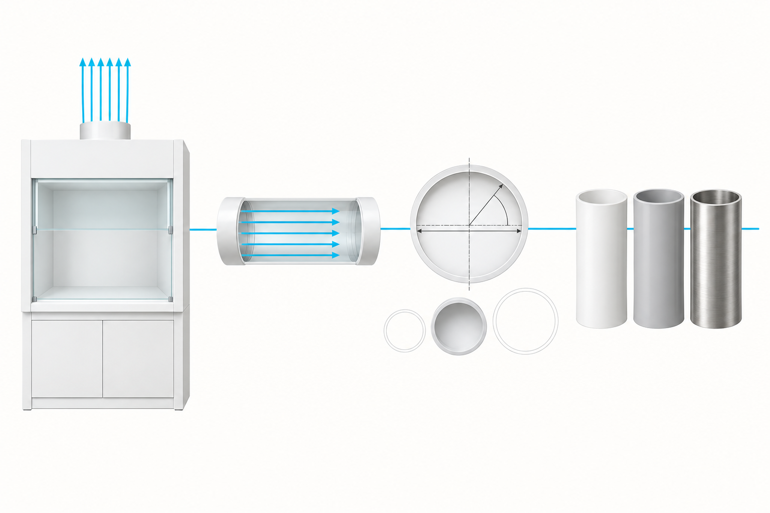
The six material candidates you will actually choose between
With diameter fixed, the material decision decides whether the duct survives its contents for twenty years or corrodes quietly behind the ceiling. Six candidates cover the practical spectrum: PP (polypropylene), PVC (and its high-temperature sibling CPVC), FRP (fiberglass-reinforced plastic), 316L stainless steel, and coated steel. The two baselines in laboratory practice are Type 1 uPVC, which resists a wide range of acids at a lower cost than stainless, and Type 316 stainless steel, which carries solvents, chloride pitting resistance and high-temperature strength. Galvanized steel — the kitchen-hood default — is not on the list for corrosion service, and a fume hood duct material choice that starts with the material catalog instead of the chemistry always ends up reselecting.
Fume hood exhaust duct materials are the place where a cheap shortcut looks attractive and a wrong choice becomes expensive later. PP, PVC and CPVC share fabrication ease and chemical breadth; FRP adds strength and higher temperature; 316L gives you fire rating, solvent resistance and chloride defense; coated steel is a middle ground whose performance is only as good as the coating. Each candidate has a row in the matrix below and a decision rule tied to the chemistry in your lab.
Material matrix rows: acids, bases, solvents, oxidizers, chlorides
Walk the material choice row by row against your actual chemistry, not against a generic “chemical duct” label. Table T5 scores the six candidates across the loads that actually kill ductwork: acids, bases, solvents, oxidizers, chlorides, temperature, condensate handling, flame-spread rating and relative cost. A few judgment calls deserve emphasis.
Oxidizers such as concentrated nitric or chromic acid are the classic PP failure; per the manufacturer compatibility guidance, polypropylene PP laboratory fume hoods handle many acid/base services at ambient temperature, but strong oxidizers, mixed streams, high temperature and long-term wet contact need a dedicated review. Chloride service points to 316L over 304, and washdown or high-temperature service pushes you to fully welded fabrication with expanded joints.
For duct hardware matching this article’s engineering language — size from airflow and velocity, record min/normal/max operating flows, controlled round-to-rectangular transitions, thermal-movement planning — see our PP/PVC ventilation ducts product line. Note that the hood material never proves the duct material: the cabinet boundary and the duct system must each be vetted for the same exhaust stream. The fume hood duct material selection is the last major decision in this guide, and it depends on everything you decided in M02–M04.
The Labconco technical article on laboratory ductwork reaches the same baseline conclusion: Type 1 uPVC and Type 316 stainless are the two starting points, with PVDC reserved for the strongest oxidizer and solvent services, and galvanized steel excluded from corrosion duty.
Flammability, temperature limits and thermal expansion
Fire rating and temperature are where plastic ducts get into trouble. NFPA 45 requires combustible duct and lining materials to meet a flame-spread index of 25 or less (per NFPA 255/ASTM E84) in the areas where the standard applies, and plastic ducts must respect their service-temperature ceilings — PP is a low-temperature material, CPVC extends the range, and FRP moves higher still while adding strength. Thermal expansion is the quiet killer of plastic runs: plastic ducts expand on the order of ten times as much as steel for the same temperature swing, which is why fixed points and sliding guides must be coordinated with the route and why flanges must never be used to force misaligned sections together or carry load. Our product documentation treats wall thickness, fabrication and support spacing as functions of size, shape, temperature and pressure — you should do the same rather than copying liquid-pipe data into a ventilation schedule.
Table T5 — Duct material selection matrix
| Performance load | PP | PVC / uPVC | CPVC | FRP | 316L SS | Coated steel |
|---|---|---|---|---|---|---|
| Acids (general) | Good (ambient) | Good | Good | Good | Good | Fair — coating-dependent |
| Bases | Good (check conc./temp.) | Good | Good | Good | Good | Fair |
| Solvents / organics | Poor–fair | Poor | Fair–good | Check resin | Good | Good (coating-dependent) |
| Strong oxidizers | Poor (dedicated review) | Fair | Fair | Check resin | Good | Fair (coating-dependent) |
| Chlorides | Fair | Fair | Fair | Check | Excellent (pitting-resistant) | Poor–fair |
| Service temperature | Low ceiling | Modest | Higher | High | High | High |
| Condensate / washdown | Slope + welded joints | Slope required | Slope required | Slope required | Best (welded, washdown-ready) | Coating-sensitive |
| Flame-spread (NFPA 45 ≤25) | Verify rating | Verify rating | Verify rating | Verify resin rating | Noncombustible | Noncombustible |
| Relative cost | Low | Low | Moderate | Moderate | High | Low–moderate |
*Note: “Good/Fair/Poor” are practice rankings; verify every material against the specific chemical, concentration and temperature in your lab. Ratings marked “verify” are application-dependent; combustible duct must still meet the flame-spread threshold in NFPA 45 where applicable.*
Before you commit a material, confirm the chemistry, temperature and condensate rows for every stream that will share the run.
Route the Duct: Negative Pressure, Slope, Drains and Cleanouts
Negative pressure: put the fan downstream of every occupied space
Routing is the fourth decision, and it starts with pressure. The exhaust fan must sit at the discharge end of the system so that the entire duct run inside the building is under negative pressure. A negative-pressure duct that leaks draws room air inward — contamination stays inside the pipe and moves to the stack. A positive-pressure duct that leaks pushes contaminated air into the ceiling space and then into occupied areas. The rule is simple: fan last, duct negative, no branch ever pressurizes a space you occupy. This is also why the exhaust system is dedicated: never connect a chemical exhaust duct to the general return-air system.
Where treatment equipment sits in the chain
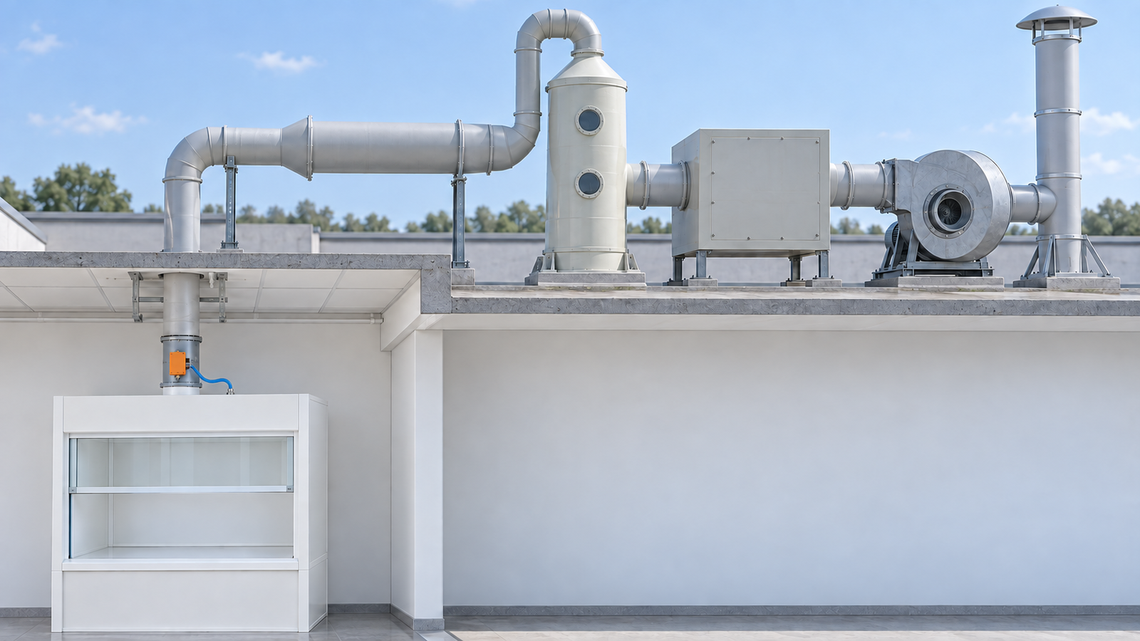
Not every chemical exhaust system runs the main duct straight into the fan. Where the chemistry, the permit or the neighbouring receptors require it, gas treatment is added before discharge — a compact packed-bed wet scrubber for water-soluble acid gases and ammonia, followed by an activated-carbon adsorber for solvents and odour. Both are duct-design inputs, not afterthoughts, because they sit in series inside the same pressure budget.
Put them between the main duct and the fan inlet, with the fan still last. That preserves the negative-pressure rule above: every length of duct inside the building stays below room pressure, so an indoor leak draws room air in rather than pushing contaminated gas out. It also means the scrubber and the adsorber are pulled through rather than pushed into, so neither has to hold positive pressure against a leaking joint.
Some designs invert this and put the fan before the scrubber to keep the fan on dry gas. That is a legitimate arrangement, but it makes the fan and the duct between fan and scrubber positive-pressure, so it belongs outside the occupied building — and the fan then has to be rated for the wet, corrosive stream passing through it.
Four duct-design consequences follow. First, resistance: the packed bed and the carbon bed each add static pressure, and both belong in the total the fan engineer sizes against — the fume hood exhaust fan sizing article computes that total from your schedule. A carbon bed’s resistance also climbs as the bed loads, so the fan needs margin at end-of-bed-life, not only on commissioning day (practice rule).
Second, the wet segment: duct between the scrubber outlet and the adsorber or fan carries saturated air and droplet carry-over, so give that segment its own slope and drain, and review its material on the wet basis rather than the dry duct basis. Third, connection size: a treatment device inlet or outlet often does not match your transport-sized main, so use a controlled transition rather than shrinking the main duct to suit a device collar. Fourth, access: beds and packing are consumables, so leave the removal path, the isolation dampers, and any observation provisions — level and packing sight glasses on a scrubber tower, for instance — in the layout from the start.
Slope, condensate drains and cleanouts
Horizontal runs must drain, not pond. Slope chemical exhaust ducts at 1/8 to 1/4 in per foot toward the hood or a low-point drain, and as a practice rule keep this slope continuous — a washdown system in a perfectly level duct cannot drain water back to the hood’s trough, and standing condensate becomes the corrosion and microbiology front. Provide condensate drain points at low points and cleanouts at direction changes and at reasonable intervals on long straight runs.
The classic resistance traps are worth noting: a 12 in 90° elbow carries about 25 ft of equivalent straight-duct length (45°: about 12.5 ft), and a zero-pressure weathercap at the stack adds almost nothing, while cone or gooseneck caps add measurable resistance. Keep at least 3 ft of straight duct before and after elbows so the velocity profile redevelops. The static-pressure arithmetic that turns these fittings into a fan selection is covered in the fume hood exhaust fan sizing article — we reference its elbow-equivalent table here rather than duplicate it.
The fume hood duct material you selected in M05 determines how aggressively condensate attacks the duct wall. PP and uPVC resist most acid condensate well; 316L stainless handles chlorides and solvents that would degrade plastic. Even with excellent slope, a material mismatch at a condensate drain point becomes the first leak in the system.
Fire dampers: what NFPA 45 actually forbids
A fusible-link fire damper in a chemical fume hood exhaust duct is a designed failure. NFPA 45 prohibits ordinary fusible-link fire dampers in these ducts because a closed damper shuts off the toxic-containment ventilation exactly when an incident is producing smoke and fumes; the duct instead penetrates walls and floors inside a fire-rated shaft, and combustible duct materials carry a flame-spread index of 25 or less where the standard applies. If fire-rated separation is needed, build the shaft — do not install a damper. For the same incident logic, never rely on the exhaust system being off during a fire; the standard’s intent is that ventilation keeps running and the building structure contains the fire.
Do not let that prohibition talk you out of the damper you actually need. A control or balancing damper in the branch — commonly at the hood exhaust collar or in the branch duct close to it — is a normal part of a laboratory exhaust system: it is how each hood’s airflow is set at commissioning and re-balanced later when the lab layout changes (standard laboratory-ventilation practice). The distinction is the function, not the word. A balancing or control damper is positioned by the balancing contractor or driven by the airflow-control loop and holds the flow you scheduled; a fusible-link fire damper closes itself on heat and shuts off the exhaust exactly when the lab needs it most.
Specify the first, and keep the second out of the duct. A controlling damper also needs pressure to work against, so its working pressure drop belongs in the same static-pressure total as the fittings — the valve window noted in module M02 is the same consideration seen from the control side. On VAV systems the collar-level duty is usually filled by a venturi valve: a self-balancing PP valve body with its actuator mounted right at the hood connection, which is why the valve hardware and the branch diameter need to be chosen as one decision — see the vav venturi valve product page for that hardware class.
Manifold versus individual runs
Finally decide whether hoods share a duct. Individual runs give chemical isolation but multiply roof penetrations, fans and energy. A manifold collects compatible hoods into one main with dilution and redundancy: the N+1 fan arrangement lets any single fan carry the full design load, and the manifold main keeps the stack velocity at 3,000 FPM or more at all operating points via bypass or motorized relief dampers. The boundary is chemical: NFPA 91 requires incompatible chemical streams to stay in separate systems — acids with organic solvents, perchloric acid with reducibles, and so on. Manifold sizing uses the simultaneous-use basis from module M02, and the control consequences — one flow change affects every hood on the manifold — are discussed in cav vs vav fume hood and in the NEBB laboratory design considerations article.
Table T6 — Duct routing physical rules
| Physical rule | Requirement (practice) | Rationale | Source reference |
|---|---|---|---|
| Negative pressure | Fan at discharge; duct below room pressure | Leaks draw inward, never into occupied space | ANSI/ASSP Z9.5 context (practice) |
| Slope | 1/8–1/4 in per ft toward hood / low point | Condensate must run out, never pond | EPA facilities guidance; Labconco (R) |
| Washdown slope | Never 0° horizontal; must drain to hood trough | Water must return to the hood drain pan | Labconco (R) |
| Cleanouts | At direction changes + intervals on long runs | Inspection and cleaning access | Industry practice (R) |
| Straight runs at elbows | ≥3 ft before and after | Velocity profile redevelopment | Labconco (practice) |
| Thermal movement | Fixed points + sliding guides; no flange-forced alignment | Plastic expands ~10× steel | Xicheng product engineering (SELF) |
| Treatment in chain | Scrubber + carbon adsorber upstream of fan, in series | Keeps duct negative; beds add resistance the fan must cover | Practice (R) |
| Fire dampers | None in chemical exhaust; fire-rated shaft penetrations | Damper closure stops toxic exhaust | NFPA 45 |
| Manifold isolation | Compatible streams only; incompatible = separate systems | Prevent mixing reactions | NFPA 91 |
Decide the routing rules now — slope, drains, cleanouts and fire-rated penetrations belong on the drawing, not on the commissioning punch list.
Special Service Ducts: Wash-Down, Perchloric and Radioisotope
Perchloric acid wash-down ducts
Some services override the normal sizing logic and demand their own duct system. Perchloric acid is the canonical case: perchlorate salts crystallize in the duct and detonate on shock, so the duct must be washable end to end — welded 316L stainless construction, no horizontal dead pockets, continuous slope to a washdown drain, and a dedicated system that is never manifolded with other hoods. The washdown water path and spray design belong to our perchloric acid fume hood requirements article; here the point is the isolation decision itself. The same logic extends to acid-digestion work where perchlorate and strong oxidizers appear together — see acid digestion vs perchloric fume hoods for when they share a system and when they cannot.
Radioisotope and high-temperature isolation
Radioisotope work adds a second isolation driver: the duct becomes a confined-surface contamination asset that must be inspected, monitored and decommissioned on its own schedule. Keep isotope exhaust separate, design for smear-and-survey access, and account for the duct in your site radiation-safety plan rather than mixing it into the general manifold. High-temperature service is the third driver: every plastic has a service-temperature ceiling, and when the process exhaust exceeds it — or when you need the fire rating of metal — FRP at its documented resin limits or welded stainless takes over.
The general rule you should apply: when the contaminant is incompatible, explosive when concentrated, radioactive, or hotter than the plastic’s rating, the decision flips from “which material for the shared duct” to “dedicated system, special material.” If your service profile is PP-compatible — many ambient acid and base services are — a polypropylene PP laboratory fume hood paired with PP duct is a coherent, cost-effective combination, but confirm the whole wetted path with the compatibility review.
Table T7 is the isolation decision table. Read it against the chemistry of every hood on your project; when a row fires, that hood’s duct leaves the shared run and gets its own system.
Table T7 — Special-service isolation decision table
| Service condition | Required construction | Dedicated system? | Manifold allowed? | Cross-reference |
|---|---|---|---|---|
| Perchloric acid | Welded 316L, washdown-capable, sloped, no dead pockets | Yes — never shared | No | Perchloric acid fume hood requirements |
| Acid digestion with perchlorate risk | Washable, dedicated review | Usually yes | Only after compatibility review | Acid digestion vs perchloric fume hoods |
| Radioisotope | Surveyable, decommissionable, monitored | Yes | No | Site radiation-safety plan |
| High temperature (> plastic ceiling) | FRP at documented resin limit or welded stainless | As required | As required by chemistry | M05 matrix, temperature row |
| Strong oxidizer / mixed stream | Dedicated chemistry review per manufacturer | Case-by-case | After compatibility review | M05 matrix |
Decide early whether any hood leaves the shared run; isolation is cheap at design stage and expensive after installation.
Common Fume Hood Duct Sizing Mistakes
Most duct failures are not calculation failures; they are habit failures. The seven mistakes below are the ones we see repeated in lab projects, each with the correction you should apply. Read the list against your own drawing before you hand the run to the fabricator — and remember that fume hood duct sizing rewards the discipline of writing every input down: the airflow basis, the velocity target, the compatibility matrix row, the static-pressure handoff.
A related cousin of mistake #7 below is sizing without accounting for leakage and simultaneous use; module M02 shows how to add those allowances to the catalog airflow so the duct is sized for the real load, not the theoretical one. The engineer who documents these inputs on the drawing leaves a record that the next project engineer, the TAB contractor, and the maintenance team can all read.
Notice what links the seven mistakes in Table T8: none of them is a hard math error. Each is a decision made with incomplete information — the collar, the peak condition, the cheap material, the missing allowance. The corrections are all decision-discipline corrections, not arithmetic corrections. When you apply them, you are applying the same four-step path from Table T1 in reverse: checking that each step was done correctly before the next step is attempted.
Table T8 — Seven common fume hood duct sizing mistakes and their corrections
| # | Mistake (anti-pattern) | Why it fails | Correction |
|---|---|---|---|
| 1 | Sizing the duct to the hood’s connection collar | Collar is often smaller than transport needs | Size by formula, then transition; never treat the collar as the duct size |
| 2 | Ignoring condensation | Hot/humid or high-boiling duty ponds liquid; corrosion + microbes | Choose upper-band velocity, continuous slope, drains at low points |
| 3 | Galvanized steel for acid duty | Fast corrosion, leaks behind ceiling | Select uPVC, PP, FRP, or 316L from the matrix |
| 4 | Horizontal 0° install with washdown | Water cannot drain back to the hood | Maintain 1/8–1/4 in per ft slope; never level washdown runs |
| 5 | Installing fusible-link fire dampers in exhaust | NFPA 45 prohibition; closure stops toxic exhaust | Fire-rated shaft instead; combustible duct ≤25 flame-spread |
| 6 | Manifolding incompatible chemicals | Mixing reactions, NFPA 91 violation | Separate systems per compatibility review |
| 7 | No duct schedule / static-pressure input to fan engineer | Fan mis-selected; system never balances | Hand over schedule + pressure budget (see fume hood exhaust fan sizing) |
Our design checklist in module M09 turns that discipline into a one-page deliverable.
Fume Hood Duct Sizing Checklist and Project Handoff
The duct schedule fields that make the handoff clean
Your last deliverable is not a drawing — it is a duct schedule. The schedule is the contract between the duct design and the fan engineer: every segment listed with its number, material, size, length, joint type, slope, cleanout locations, pressure loss and support spacing. Fill it out as you finish each module of this guide and you will hand the fan engineer a complete static-pressure input instead of a vague “12 in duct” mark on the plan. The connection to the fume hood exhaust fan sizing article is explicit: that article computes the total static pressure from your schedule’s fittings and lengths; this article produces the schedule itself.
The schedule is also the document your fume hood installation requirements package references: the installer checks that every segment matches the schedule before it is concealed. When the job is complete, the schedule becomes the as-built record that the maintenance team and the next project engineer both inherit.
Pre-commissioning checks before the fan engineer takes over
Before handoff, run the pre-commissioning checks in Table T9. Walk the route for slope and cleanout access. Confirm negative pressure orientation at every branch. Verify the material matrix row against the actual chemical inventory — if the chemicals changed after the schedule was written, the schedule must be re-reviewed. Confirm the simultaneous-use basis still holds. Check fire-rated penetrations. Ensure the ASHRAE 110 fume hood test plan is scheduled so containment is verified before the lab is occupied. Commissioning is where the numbers meet the building: the TAB contractor sets balancing dampers so each hood receives its scheduled airflow, and the ASHRAE 110 test verifies containment. Close the loop by filing the schedule with the fan engineer’s calculation and the test report in the lab’s O&M documentation.
The ANSI/ASSP Z9.5 laboratory ventilation standard is the framework behind this handoff discipline — the engineer, the TAB contractor and the owner each sign off on a slice of the record.
Table T9 — Fume hood duct sizing design checklist
| # | Check | Pass criterion | Done? |
|---|---|---|---|
| 1 | Airflow basis | Catalog CFM + named allowances recorded (M02) | ☐ |
| 2 | Velocity target | Band selected from contaminant phase; R confirmed (M03) | ☐ |
| 3 | Diameter | D = √(4Q / πV); standard size; actual velocity in band (M04) | ☐ |
| 4 | Material matrix | Every chemical inventoried against matrix row; CTA-compatible (M05) | ☐ |
| 5 | Routing | Negative pressure confirmed; slope continuous; drains at low points (M06) | ☐ |
| 6 | Isolation | Perchloric/washdown/radioisotope/high-temp decided (M07) | ☐ |
| 7 | Fire safety | No dampers; shaft penetrations; flame-spread ≤25 where required (NFPA 45) | ☐ |
| 8 | Duct schedule | Segment fields complete; handed to fan engineer (M09 + FH-B19) | ☐ |
| 9 | Commissioning | TAB balanced; ASHRAE 110 test scheduled; records filed | ☐ |
That is the full path: airflow from the catalog, velocity from the contaminant, diameter from the formula, material from the chemistry, routing from the physics. Done in this order, fume hood duct sizing is repeatable, reviewable and defensible — and the checklist above is the artifact you leave behind.
You can now hand the fan engineer a complete duct schedule and keep this checklist as the record for commissioning.
FAQ: Fume Hood Duct Sizing Questions
What is the standard duct velocity for a chemical fume hood exhaust?
The practice range for gases and vapors is 1,000–2,000 FPM, with 1,500–1,800 FPM the common sweet spot; condensation and high-boiling vapors push you to the upper end of that band. Light dust is roughly 2,500 FPM; heavy or wet dust needs 3,500–4,000 FPM. These are practice ranges (R) — confirm the exact value with your project engineer and against the ACGIH Industrial Ventilation manual.
Can I use galvanized duct for a fume hood?
For corrosive chemical service, no. Galvanized steel corrodes quickly in acid fume and vapor service, and the combustible rating of the coating is also a concern where NFPA 45 applies. Select uPVC, PP, FRP, or 316L stainless steel from the material matrix. Galvanized steel is the kitchen-hood default, not the laboratory-hood default.
What size duct do I need for 1,000 CFM?
At a 1,800 FPM target, the theoretical diameter is about 10.1 in, so you select the standard 12 in duct and the actual velocity is 1,273 FPM — inside the gas/vapor band. Use Table T4 or the formula D = √(4Q / πV) for other airflows and other targets; the answer depends on the velocity band you choose, not just the airflow.
Should round or rectangular duct be used?
Round is the default: it moves the airflow at the lowest pressure loss, sheds condensate predictably, and is easier to seal. Rectangular is a space solution for tight plenums. When you use rectangular, compare sections by hydraulic diameter (4A / wetted perimeter) and keep the aspect ratio at 4:1 or lower as common practice; use a controlled transition between round and rectangular, and state the end sizes and alignment datum on the drawing.
Can two fume hoods with different chemicals share one duct?
Only if the streams are compatible. NFPA 91 requires incompatible chemical systems — acids with organic solvents, perchloric acid with reducibles, and similar pairs — to stay in separate duct systems. Compatible streams can be manifolded with dilution and N+1 redundancy; see module M06 for the rules and Table T7 for the isolation decisions.
Why are fire dampers prohibited in fume hood exhaust ducts?
NFPA 45 prohibits ordinary fusible-link fire dampers in chemical fume hood exhaust ducts because a closed damper shuts off the toxic-containment ventilation exactly when an incident is producing smoke and fumes. The correct approach is a fire-rated shaft penetration, with combustible duct materials meeting a flame-spread index of 25 or less where the standard applies. Never rely on the exhaust being off during a fire; the standard’s intent is that ventilation keeps running while the building structure contains the fire.
Final Verdict
Fume hood duct sizing is the quiet half of every lab exhaust project. The formula is a few characters long; the decision is not. Start from the catalog airflow, hold the transport velocity band, verify the actual velocity at the standard diameter, prove the material against the full chemistry, and route the duct for pressure, drainage and fire. Do that, and the fan engineer’s job — and the ASHRAE 110 test — become confirmations of a decision already made correctly. Skip a step and the duct will tell you later, from behind a closed ceiling, where the problem is most expensive to fix. Size the duct like it is a safety device, because it is.
Before you sign off, work the four steps once more against the checklist and file the schedule next to the commissioning record — done in that order, fume hood duct sizing becomes a decision you can defend rather than a guess the next engineer inherits.
Leave a Reply