




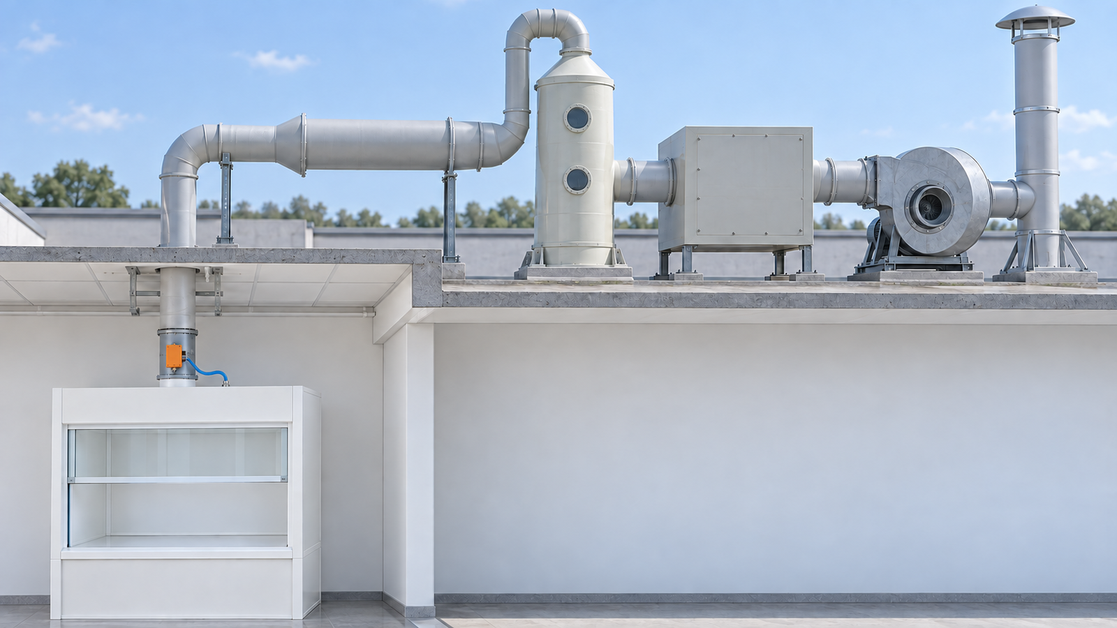
Key Takeaways
- Fume hood exhaust fan sizing is a decision about three linked outputs at once: the airflow the hood needs at its operating sash, the static pressure the whole system adds, and a fan operating point the controls can hold.
- The method runs in four steps: pin down required airflow, add up system static pressure, pick the fan on its curve, then match the fan to the control scheme.
- A fan chosen too small cannot hold face velocity, so containment fails quietly at the hood face. A fan chosen too large brings noise, wasted energy, and a turndown dead zone on VAV systems.
- The selection is proven after installation: test-and-balance verification plus a quantitative airflow monitor with a low-flow alarm closes the loop.
What Fume Hood Exhaust Fan Sizing Actually Decides
Fume hood exhaust fan sizing is the step where a laboratory ventilation project stops being a room with a hood in it and becomes a system with a guaranteed face velocity. The fan is the last component you specify and the first one blamed when containment drifts, so the selection deserves a method, not a rule of thumb.
The decision produces three outputs, and each one constrains the next:
- Required airflow. The CFM the hood needs with the sash at its approved operating height, before allowances for leakage and standby modes.
- Total system static pressure. The hood’s own resistance plus the resistance added by every foot of duct, every elbow, and the stack cap between hood collar and discharge.
- A holding operating point. A position on the fan curve where the fan delivers that airflow against that static pressure, and where the control scheme can keep it pinned through sash movement and filter loading.
Each output has a failure direction. Undersize the fan and the hood slides below the containment floor: CCR Title 8 §5154.1 (c)(1) requires an average face velocity of at least 100 fpm with no point below 70 fpm, with measurements within 1 inch of the perimeter excluded. A marginal fan may pass on day one and lose the floor as ductwork accumulates resistance. Oversizing fails differently. The fan is louder than the room tolerates, it burns fan energy around the clock, and on a VAV system it can park the minimum-flow point where the fan cannot modulate down cleanly, so the turndown strategy dies on the fan curve before the controls get a say.
| Sizing input | Where the number comes from | What it decides |
|---|---|---|
| Required airflow (CFM) | Hood catalog tables at the operating sash, plus project allowances | The airflow coordinate of the fan duty point |
| Hood static pressure | The hood manufacturer’s pressure-loss tables | The fixed resistance term in the static-pressure budget |
| Duct static pressure | An equivalent-length calculation over the actual duct routing | The variable resistance term, driven by elbows and stack height |
| Control scheme (CAV, VAV, manifold) | The building’s ventilation design decision | What the fan must do besides deliver one point |
You now have the shape of the decision: three outputs, two failure directions, and four inputs. The next four sections turn each input into a number that belongs on a fan schedule.

Step 1 — Pin Down the Required Airflow
Step 1 answers the first question in any fan selection: what is the airflow the hood needs? The formula itself is one multiplication — average face velocity times the sash opening area — and the full method, including how to measure the net opening, is covered in our fume hood airflow calculation guide. Run it at the operating sash height, not the fully open position, because that is the caliber the hood will be used and inspected at.
For the 6-foot hood this article follows, the bare calculation gives 6 ft × 1.5 ft of opening = 9 ft², and 9 ft² × 100 fpm = 900 CFM. The 100 fpm average with a 70 fpm floor at any point comes from CCR Title 8 §5154.1 (c)(1); the full velocity requirements, including how the perimeter exclusion works, are detailed in our fume hood face velocity requirements article.
The bare number is not the fan number. A bypass hood passes room air through its bypass opening whenever the sash closes, so the exhaust system must carry both the face airflow and the bypass airflow. Labconco’s catalog tables for a 6-ft bypass hood at an 18-inch sash and 100 fpm list 1,120–1,180 CFM of total exhaust at 0.28–0.31 in. of hood static pressure (catalog-table values). The same tables list 960 CFM at 0.24 in. for a 5-ft hood and 1,660 CFM for an 8-ft hood. The 220–280 CFM gap between the bare 900 and the catalog range — simple subtraction from those two figures — is the bypass allowance, and it is why the fan is bought against the catalog row, not the arithmetic.
Allowances then adjust the working number, and each one has a defined caliber:
| Allowance | Working caliber | Source caliber |
|---|---|---|
| Bypass airflow | Use the catalog exhaust CFM, not the bare face-velocity product | Labconco catalog-table values |
| Duct leakage | About 15 CFM for SMACNA Seal Class C / Leakage Class 8 | Practitioner estimate (field example) |
| Penetrations and gaps | Add the free area of electrical pass-throughs and hood leakage paths | Practitioner estimate |
| VAV standby airflow | 60 fpm only with an automatic control system, ASHRAE 110-1995 tracer-gas performance of AU 0.1 ≤ 4.0, and record keeping | CCR Title 8 §5154.1 (c)(2) |
The leakage allowance is not a rounding error. In the practitioner field example behind that number, a valve selected at 900 CFM delivered about 98 fpm at the hood face once roughly 15 CFM of duct leakage was paid for first — under the containment floor with the design untouched. And the standby line has teeth: dropping to 60 fpm overnight is compliant only when all three conditions of (c)(2) are met and documented.
Two more allowances belong on the list for shared systems. A manifold carries a minimum total flow set by stack dispersion and fan stability, and each hood inherits part of that floor even with every sash closed. Any hood already committed to the same fan in a future phase is a real airflow demand from day one of the fan selection, not a someday number.
The catalog exhaust figure, the leakage and penetration allowances, and the standby caliber together determine the airflow number that Step 2 carries into the static-pressure budget.
Step 2 — Add Up the System Static Pressure
The fan does not see the hood alone; it sees everything between the hood collar and the open air. System static pressure is the sum of two terms — the hood’s own resistance and the resistance of the duct run — and getting the sum wrong in either direction makes the operating point you pick in Step 3 fiction.
Hood static pressure comes from the catalog. The 6-ft bypass hood in this example carries 0.28–0.31 in. w.g. at the 18-inch sash operating point (catalog-table values). When a range is given, the higher end is the safer read — and the budget should err high in one term or the other: the worked example below takes the hood row at 0.28 in. and recovers the margin in the duct term instead, by rounding up to the 1,250 CFM loss row.
Duct static pressure comes from the equivalent-length method, and the inputs are simple to collect. Measure every foot of straight duct, vertical and horizontal. Count the fittings: at 12-inch duct, a 90° elbow is worth 25 ft of straight duct and a 45° elbow is worth half of that, 12.5 ft. Add 5 ft for a zero-pressure weathercap at the discharge (Labconco’s blower-sizing guide publishes the fitting table). Choosing the duct diameter is a design task of its own — the duct-sizing article in this series covers it — so for fan selection, treat the diameter as a fixed input and count fittings against it.
Loss per foot comes from the same guide’s tables: 1,000 CFM in 12-inch duct costs 0.0018 in. w.g. per ft, and 1,250 CFM costs 0.0027 in. per ft.
Consider a worked example for the 6-ft bypass hood, routed through 40 ft of straight 12-inch duct with four 90° elbows, one 45° elbow, and a weathercap:
| Item | Value | Source |
|---|---|---|
| Hood duty airflow | 1,180 CFM | Labconco catalog-table values, high end of the 6-ft bypass row |
| Hood static pressure | 0.28 in. w.g. | Same catalog row |
| Straight 12-inch duct | 40 ft | Example project routing |
| Four 90° elbows | 4 × 25 ft = 100 ft equivalent | Labconco blower-sizing guide |
| One 45° elbow | 12.5 ft equivalent | Same guide |
| Weathercap | +5 ft equivalent | Same guide |
| Total equivalent length | 157.5 ft | Sum of the routing rows |
| Duct loss rate | 0.0027 in. w.g. per ft | Same guide, 1,250 CFM row |
| Duct static pressure | 157.5 × 0.0027 ≈ 0.43 in. w.g. | Worked arithmetic |
| Total system static pressure | 0.28 + 0.43 ≈ 0.71 in. w.g. | Hood term + duct term |
Rounding the airflow up to the 1,250 CFM loss row is deliberate: 1,180 CFM sits between table rows, and the higher loss rate buys margin without changing the fan. Two habits keep this step honest. Walk the routing before you count it, because a duct that detours around a beam or a fire damper adds real equivalent length that no drawing shows. And keep the hood’s accessories in mind when reading the catalog row, because the row assumes the hood as configured in the table, not the hood as optioned.
Your next step: carry the duty point this budget produces — 1,180 CFM at roughly 0.7 in. w.g. — to a fan curve in Step 3, and refuse any fan selection quoted against CFM alone.
Step 3 — Pick the Fan on the Curve
A fan curve plots airflow on one axis and static pressure on the other for a given fan at a given speed. Step 1 produced 1,180 CFM; Step 2 produced roughly 0.7 in. w.g. The selection task is to find a fan whose curve passes through that duty point comfortably inside its performance band, not at the edge.
Four habits separate a durable selection from a marginal one.
Pick the lowest practical impeller speed. Among fans that can hit the duty point, the one doing it at the lowest RPM is the quieter fan, and it usually holds more speed in reserve for future filter loading or system additions. Manufacturer selection guidance for laboratory exhaust systems states it plainly: select the fan that delivers the target CFM at the required static pressure at the lowest practical wheel speed, and cross-check the result on the selection chart before you buy.
Match construction to the chemistry. Acid-laden or solvent-heavy exhaust pushes the selection toward corrosion-resistant polymer or FRP construction; coated steel suits milder, well-diluted duty. The material call applies to the duct run just as much as the fan — specifying matching PP and PVC duct components is part of the same chemistry decision, and the hardware side of that call is covered in our pp pvc ventilation ducts product line.
Correct for temperature and altitude before trusting the curve. Published curves assume standard air. Hot exhaust streams and high-altitude sites both change air density — the U.S. EPA’s performance-requirements document for laboratory fume hoods requires testers to determine exhaust air temperature, elevation, and barometric pressure and correct for the prevailing air density, and a fan selection deserves the same correction. Apply the fan manufacturer’s correction factors first, then re-read the duty point on the corrected curve.
Know the drive you are buying. Belt drive remains common on constant-volume laboratory exhaust installations (NEBB) and brings a routine maintenance obligation — periodic inspection, tensioning, and eventual belt replacement as ordinary drive service. Direct drive removes the belt as a wear item but fixes the speed relationship between motor and wheel, which matters once a variable-frequency drive enters the plan. That question belongs to Step 4.
| Selection factor | What it rules in or out | Where it bites |
|---|---|---|
| Duty point position | Fans whose performance band contains 1,180 CFM at ~0.7 in. w.g. | A point near the curve’s edge starves as resistance grows |
| Impeller speed | Lower-RPM selections win on noise and reserve | Every operating hour of the lab |
| Construction material | Polymer/FRP versus coated steel | Corrosive or solvent-laden exhaust streams |
| Drive type | Belt (serviceable, common on constant volume) versus direct | Maintenance budget and any future drive retrofit |
| Density correction | Whether the published curve still describes the installed air | Hot exhaust, high altitude, low barometric pressure |
| Control compatibility | Whether the fan line tolerates VFD service | VAV and manifolded systems, decided in Step 4 |
Choose the fan that holds the corrected duty point inside its performance band at the lowest practical speed in the right material for the chemistry — that is the whole of Step 3, and anything quoted without a curve is a guess wearing a part number.
Step 4 — Match the Fan to the Control Scheme
A fan that is perfect at one duty point can still be wrong for the system around it. The control scheme defines what the fan must do besides deliver one point, and each scheme carries its own fan-side constraints.
A dedicated constant-volume hood on a bypass-style cabinet is the classic pairing: the hood bleeds the surplus when the sash closes, and the fan runs one operating point all day at constant speed. The fan-side requirement is stability at a single point — no turndown, but no energy relief either.
A manifolded constant-volume system puts several hoods on one fan through balancing valves or airflow control valves. Those valves live inside a pressure window of roughly 0.3–3 in. w.g., with fast-acting valves accepting up to 6 in. w.g. (NEBB). The fan must hold a riser pressure the valves can actually work in; let the pressure drift outside the valve window and every hood on the manifold loses balance at once.
A VAV system layers hood valves, a duct-pressure control loop, and a drive-equipped fan. Greenheck’s FA124-05 bulletin frames the three control layers and records the two historical reasons fan speed reduction was avoided: reduced stack exit velocity and a weaker, lower-rising discharge plume. The sizing consequence is narrow but absolute — variable-frequency drive service belongs on fan lines engineered for laboratory exhaust duty, which hold safe exit velocity at reduced flow, not on general-purpose fans retrofitted with a drive.
A bypass valve holding constant static pressure in the riser keeps the fan pinned to a stable minimum-flow point while the hood valves trim to demand. Whether the building should run CAV or VAV at all is a system-selection question our CAV vs VAV fume hood article takes up; the fan-side task here is only to know which constraints the chosen scheme imposes.
Standby and turndown are where undersized thinking shows up. The 60 fpm standby setpoint is lawful only under the three conditions of CCR Title 8 §5154.1 (c)(2) covered in Step 1. And turndown has a floor: in a practitioner example, an 8-ft hood drops from 1,600 CFM occupied to 500 CFM at 60 fpm standby — roughly a 31 percent turndown (practitioner estimate) — and the fan must sit stably at that minimum-flow point instead of hunting around it.
Redundancy changes the duty point itself. For critical applications, N+1 means every fan in the group is sized to carry full system flow alone (NEBB and Greenheck both state it), so each fan is selected for the worst case, not the average one.
The energy stakes behind all this are concrete: Greenheck’s FA124-05 energy split for a temperate-climate laboratory puts roughly 33 percent of lab energy into supply-air cooling, 33 percent into supply fans, 17 percent into reheat, and 17 percent into the exhaust fan. How much conditioned makeup air the room supplies is the makeup-air article’s subject in this series; the fan-side point is only that the exhaust fan cannot be selected in ignorance of it. On the hood side of a VAV scheme, the valve is part of the same selection chain — see the vav venturi valve for that hardware class.
| Control scheme | Fan-side requirement | What breaks if ignored |
|---|---|---|
| Dedicated CAV, one bypass hood | One stable operating point, constant speed | No standby energy relief, but nothing exotic either |
| Manifolded CAV with valves | Riser pressure held inside the valve window (~0.3–3 in. w.g., NEBB) | Every hood unbalances together when pressure drifts |
| VAV with VFD | Drive-rated lab-exhaust fan line plus a bypass valve for constant riser pressure | Exit velocity and plume rise degrade at reduced speed (Greenheck FA124-05) |
| VAV standby at 60 fpm | Fan stable at the minimum-flow point | Turndown dead zone and standby non-compliance ((c)(2)) |
| N+1 manifold redundancy | Each fan sized for full system flow | Redundancy that exists only on paper |
Decide this cycle: name the scheme the building will run, then size the fan for that scheme’s constraint — a single point, a valve window, or a stable minimum-flow floor.
Sizing Margins and the Mistakes That Kill the Selection
Margin belongs in the allowances, not in the fan. The distinction matters because the two ways of carrying margin fail differently, and only one of them is reversible on paper.
Margin that belongs in the calculation is specific: duct leakage (about 15 CFM under SMACNA Seal Class C / Leakage Class 8, per the practitioner field example cited in Step 1), electrical penetrations and hood leakage paths, purge-mode capacity where the laboratory protocol demands it, and any committed future hoods on the same fan. Each enters the airflow or static-pressure budget as a named line with a source, which means each can be questioned, audited, and removed when the design changes.
Margin that does not belong in the calculation is a bigger fan than the duty point needs. Oversizing is the most tempting error in the trade because it feels like safety. What it buys instead is noise the room lives with on every shift, fan energy on every operating hour, and — on VAV systems — a minimum-flow point the fan cannot reach cleanly, which converts the standby strategy into a turndown dead zone. The climate bill is easy to state: single-pass conditioned air costs roughly $7–10 per CFM (practitioner estimate), so an over-selected fan pays for air it never needed to move, every hour, in addition to its noise.
| Mistake | What it produces | The correction |
|---|---|---|
| Selecting on CFM alone | A fan that cannot deliver its CFM against real static pressure | Select at CFM and total system static pressure together |
| Dropping hood static pressure from the budget | 0.28–0.31 in. w.g. silently missing from the sum | Read the hood’s catalog pressure row first (catalog-table values) |
| Letting a VAV fan fall below its minimum-flow point | Instability and failed turndown at standby | Hold the floor with a bypass valve and a drive-rated fan line |
| Skipping temperature and altitude correction | A curve that no longer describes the installed air | Apply the manufacturer’s density corrections before selecting |
| Positive-pressure duct inside the occupied building | Leaks push contaminated air into the room | Keep the fan downstream so the indoor run stays negative; blowers outdoors or in service rooms, with a narrow exception for sealed standalone systems ((e)(6)) |
| Buying a bigger fan than the duty point needs | Noise, energy, VAV turndown dead zone | Put margin in the allowances; select to the corrected duty point |
| Red line | Any selection not verified on a fan curve at the total system static pressure | No curve verification, no purchase order |
Before you approve the fan schedule, run every row of that table against the selection you are about to buy — six mistakes and one red line are cheaper to catch on paper than in the stack.
Special Conditions: Corrosion, Heat and Odd Hood Geometries
Some hoods refuse the standard selection path, and each refusal has a defined handling rather than a workaround.
Perchloric acid work sits at the top of the corrosion spectrum and outside the general method. Perchloric hoods belong to dedicated washdown systems with their own duct and fan, never manifolded with general laboratory exhaust (standard laboratory-ventilation practice), and their material and safety requirements are their own subject — the perchloric-acid hood article in this series covers that boundary in full. The same isolation logic applies to radioisotope work, where filtration and monitoring requirements change the duct and fan arrangement (standard laboratory-ventilation practice); that boundary belongs to the radiation-lab article in this series.
Heat and altitude change the air, not the method. Hot exhaust streams and high-elevation sites both thin the air the fan sees, which moves the operating point on any published curve; the correction step from Step 3 applies before the duty point means anything. Purge mode adds a second point to check: an emergency purge asks for capacity above the normal duty point, and the fan’s curve has to contain that higher point too, not just the everyday one.
Odd geometries attack the first step instead of the third. Combo sashes, dual sashes, and walk-in hoods make the operating sash opening genuinely hard to define — a walk-in with the door closed presents no sash opening to average a velocity across at all (practitioner observation). For these hood types, fix the opening caliber with the hood manufacturer in writing before Step 1, or the whole four-step chain inherits a wobbly first number.
| Condition | Implication for the selection | Action |
|---|---|---|
| Perchloric acid duty | Dedicated washdown system; no manifold sharing | Separate fan and duct; follow the perchloric hood requirements in that article of this series |
| Radioisotope duty | Filtration and monitoring change the duct arrangement | Dedicated run; see the radiation-lab article in this series |
| Hot exhaust or high altitude | Published curve no longer describes the installed air | Apply density corrections before reading the duty point |
| Purge mode in the protocol | Capacity demand above the normal duty point | Verify the fan’s curve contains the purge point as well |
| Combo, dual sash, or walk-in hoods | The operating opening is hard to define | Fix the opening caliber with the hood manufacturer before sizing |
Select for the chemistry and the geometry first, apply the corrections second, and the fan curve will still be waiting when the special conditions are settled.
Commissioning: Proving the Sizing Was Right
On paper the selection is finished; in the building it is still a claim. Closing it takes a defined division of labor and a fixed measurement caliber.
The responsibility line is set by industry practice: a licensed engineer selects and specifies the fan, and a test-and-balance (TAB) contractor measures and balances the installed system to the design airflow (NEBB). The professional who buys the fan and the professional who proves it are different on purpose, and the specification should keep their scopes separate rather than blurred.
The measurement caliber matters as much as the responsibility line. A VelGrid averaged across the hood face tends to disagree with a calibrated hot-wire anemometer by 5–10 percent on re-measurement (practitioner estimate), which is one reason acceptance work runs on hot-wire instruments and the grid serves as a screening tool. If commissioning numbers and handover numbers were taken with different instruments, expect a 5–10 percent disagreement before you go looking for a real change in the hood.
The monitoring layer turns the alarm into a permanent witness. CCR Title 8 §5154.1 (e)(3)(A) requires a quantitative airflow monitor or alarm, with the low-flow alarm set below 80 percent of required airflow. Placement and discharge are part of the proof too: blowers belong outside the building or in service rooms, with a narrow exception for single independent systems in corrosion-resistant sealed ductwork ((e)(6)), the stack discharges vertically at least 7 ft above the roof ((e)(4)(D)), and the duct run between hood and fan stays negative so any leak pulls room air into the duct instead of pushing contaminants out of it (manufacturer practice for laboratory exhaust). For the installation-side details — curbs, access, clearances — see our fume hood installation requirements guide, and for the acceptance-test protocol itself, see the ASHRAE 110 fume hood test article.
| Commissioning checklist item | Caliber | Pass condition |
|---|---|---|
| Face velocity survey | Hot-wire instrument at the operating sash | At least 100 fpm average, no point below 70 fpm, 1-inch perimeter excluded ((c)(1)) |
| Fan duty point vs design | Measured airflow and static pressure against the selection sheet | Installed point matches the corrected duty point within TAB tolerance |
| Leakage and penetrations | Duct sealing class confirmed; hood penetrations closed | Step 1 allowances hold in the as-built system |
| Airflow monitor and alarm | Quantitative monitor per (e)(3)(A) | Alarm set below 80 percent of required airflow and function-tested |
| Stack and fan placement | Roof discharge geometry | Vertical discharge at least 7 ft above the roof ((e)(4)(D)); fan outdoors or in a service room ((e)(6)) |
| Standby compliance | If a 60 fpm standby is claimed | Automatic control, ASHRAE 110-1995 AU 0.1 ≤ 4.0, and records ((c)(2)) |
Treat the checklist as the receipt for the four steps before it. A fan sized on the operating-sash caliber, budgeted at the full system static pressure, selected on its curve at the corrected density, and matched to the control scheme will pass every line above without drama. A fan that fails one of these lines is telling you exactly which step was skipped, and the fix should lead back to that step’s number rather than to another purchase.
When every line of the commissioning checklist is closed and documented, you can state that the fume hood exhaust fan sizing was done correctly — the installed fan, the measured face velocity, and the alarm threshold all match the numbers on the selection sheet. That is the point of the whole method: fume hood exhaust fan sizing earns its proof at commissioning, not at purchase.
Fume Hood Exhaust Fan Sizing: FAQ and Final Verdict
How many CFM does a fume hood need?
Start at the operating sash, not the nameplate. A 6-ft hood with an 18-inch operating sash at 100 fpm works out to 900 CFM by bare arithmetic, but the catalog row for a 6-ft bypass hood at the same conditions reads 1,120–1,180 CFM of total exhaust (catalog-table values), because the bypass airflow rides on top of the face airflow. The containment floor itself is 100 fpm average with no point below 70 fpm (CCR Title 8 §5154.1 (c)(1)). Size to the catalog row plus named allowances, never to the bare product.
What static pressure should I size the fan for?
The sum, not the hood. Take the hood’s catalog static pressure — 0.28–0.31 in. w.g. for the 6-ft bypass example (catalog-table values) — add the duct losses by the equivalent-length method, and select at the total, which came to roughly 0.71 in. w.g. in this article’s worked example. On valve-controlled systems, remember the valves themselves work inside a pressure window of about 0.3–3 in. w.g. (NEBB), so the fan’s pressure has to land where the hardware can follow.
Can one fan serve several fume hoods?
Yes, and it is the normal arrangement: a manifolded system with balancing valves or airflow control valves, one fan carrying the combined flow. For critical applications the redundancy standard is N+1 — every fan sized to carry full system flow alone (NEBB, Greenheck). That changes the duty point each fan is selected for, not just the duct layout on the roof.
Does a VAV system change fan sizing?
It changes the constraints more than the airflow. The fan must be a drive-rated laboratory-exhaust line with a bypass valve holding constant riser pressure, because slowing a generic fan costs stack exit velocity and plume rise (Greenheck FA124-05). Turndown is the other constraint: an 8-ft hood dropping from 1,600 CFM occupied to 500 CFM at a 60 fpm standby is roughly a 31 percent turndown (practitioner estimate), and the fan has to sit stably at that floor rather than hunt around it.
Why is my fume hood fan so loud?
Usually because it is running faster than the duty point requires. When margin gets stacked into the wheel instead of into the allowances, the fan over-speeds for years and the room pays for it on every shift. The remedy is at selection time: among fans that hold the duty point, take the lowest practical impeller speed, and confirm that vibration isolation and flexible connections were part of the installation rather than extras.
Who is responsible for sizing the fan?
The division of labor is defined in industry practice: a licensed engineer selects the fan, and a TAB contractor balances and verifies the installed system against the design airflow (NEBB). Your role as the lab operator or project manager is to own the inputs — operating sash caliber, chemistry, duct routing, control scheme — and to hold the commissioning checklist, so the handoff between the two professionals has no gaps in it.
Final Verdict
Fume hood exhaust fan sizing is not a table lookup; it is a four-step chain of judgments. Pin the airflow at the operating sash with real, named allowances. Add the system static pressure from the hood’s catalog row through the stack cap. Pick the fan that holds that duty point inside its curve at the lowest practical speed in the right material for the chemistry. Then match it to a control scheme that can hold the point — constant volume, manifold, or VAV with a drive-rated fan.
Until the hot-wire survey and the 80 percent alarm prove otherwise, the selection remains a claim, so commission it like one. Run the chain in order and the fan you buy will be the fan the hood needs; skip a step, and the shortfall will surface later as noise, wasted energy, or a containment reading nobody can explain. Treat fume hood exhaust fan sizing as a decision worth making once, deliberately — and decide it with the method, not a rule of thumb.
Leave a Reply