




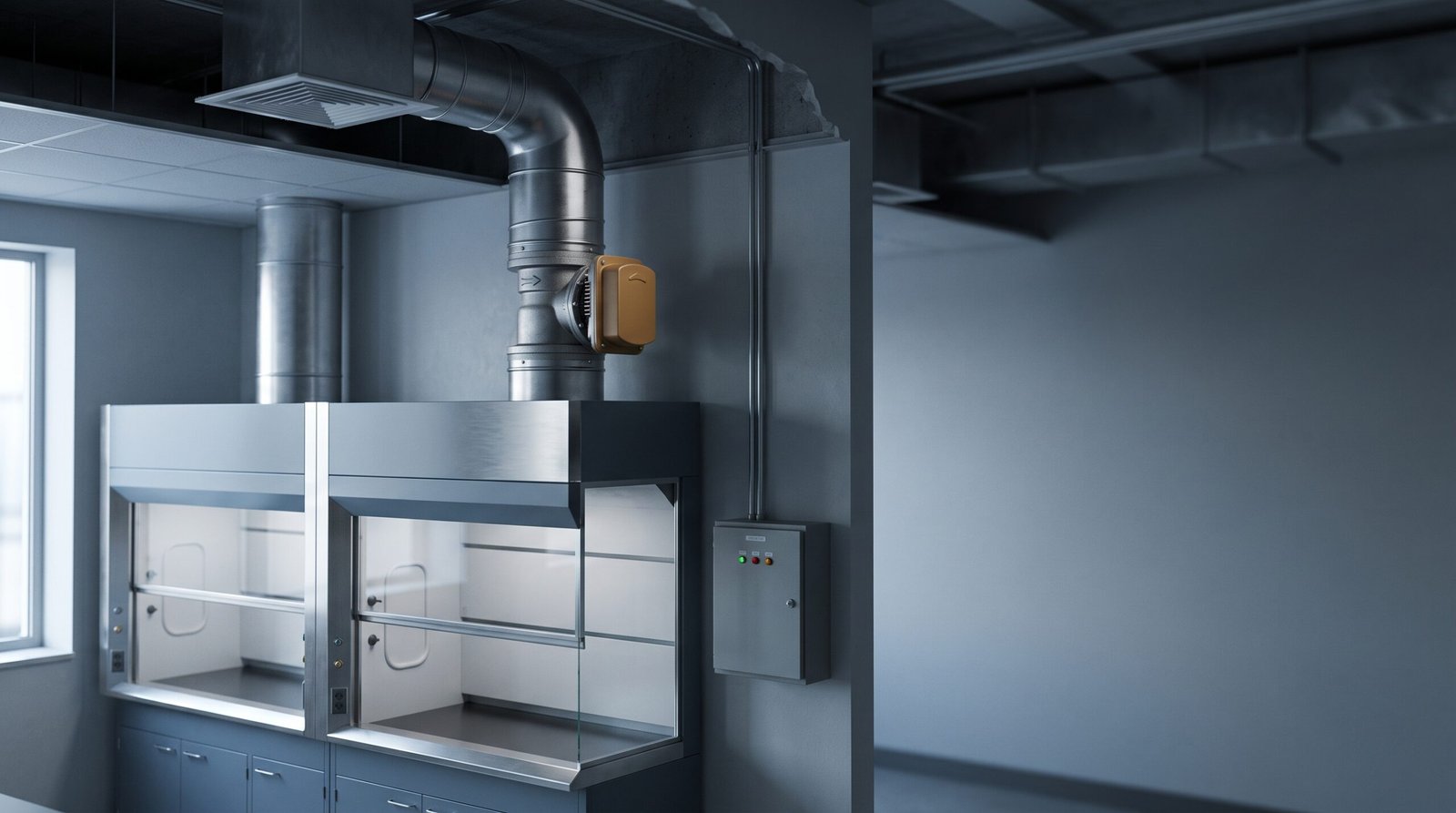
Key Takeaways
- A laboratory ventilation sequence of operation is a written engineering deliverable that specifies, for each device and mode, what the device shall do during normal operation and what position it shall move to when a component fails. — This definition establishes the sequence as an actionable document, not a description.
- The sequence must be settled before the bid because the actuator’s fail position determines whether it needs a spring-return mechanism, a supercapacitor for fail-to-last-position, and what alarm contacts it must bring back to the building automation system. — CU Anschutz requires submission two weeks before bid; Yale states a generic sequence is not acceptable.
- Three named fail positions — normally open-maximum, normally closed-minimum, and last position — are all legal; the choice is driven by containment requirement and room-pressure hierarchy, not by energy preference. — Texas A&M design standard defines the three options and the “maintained without external influence” condition.
- Every monitored point has one of two jobs: alarm (announce) or action (change the system); merging the two creates either nuisance shutdowns (transient fluctuations trigger unnecessary changes) or silent loss (failures persist unnoticed). — Low hood flow, room pressure drift, and supply-temperature fluctuation shall only alarm; loss of containment, face-velocity excursion, and critical-component failure shall trigger automatic actions.
- The five-part package you hand your controls contractor consists of mode definitions, device-by-device fail positions, the alarm-and-action split, acceptance criteria, and a change-management record. — These five parts together make the sequence bid-able, programmable, and verifiable.
A laboratory ventilation sequence of operation is the written engineering deliverable that tells your controls contractor what each valve, damper, and fan shall do during normal operation and what position it shall move to when a component fails. The sequence you write specifies the modes, assigns fail positions driven by containment and pressure hierarchy, separates alarms from automatic actions, and includes the verification tests that prove the system behaves as written.
The Sequence of Operation Is a Deliverable, Not a Description
What the Document Is, in One Sentence
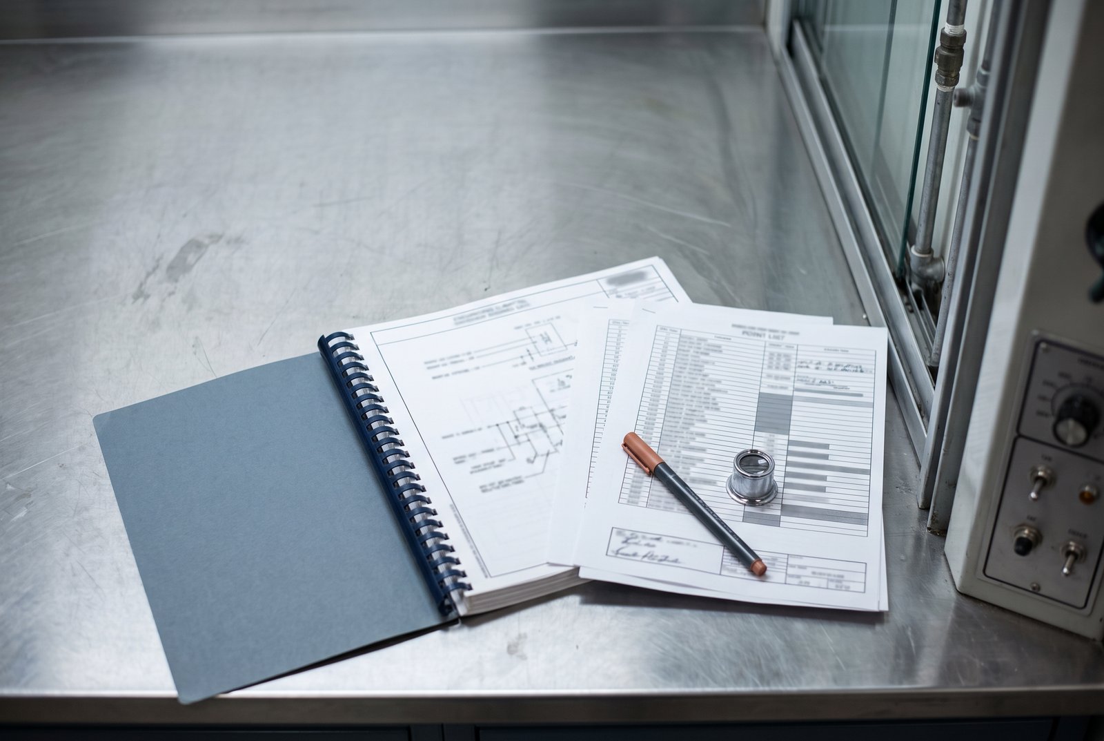
A laboratory ventilation sequence of operation is a written engineering deliverable that specifies — for each controlled device and each operating mode — what the device shall do during normal operation, what position it shall move to when a component fails, and who confirms that response. It is not a description of what the system might do; it is the document your controls contractor needs to price actuators, wiring, and programming, and that the owner’s engineer reviews before the bid. Without a complete sequence, you cannot know whether a spring-return actuator shall fail open to maximum position, fail closed to minimum position, or hold its last position — and you cannot know how many hours of debugging will be needed after startup to make the system respond as required.
Why It Belongs Before Startup
If you hand your controls contractor a sequence after the bid, every change to valve type, wiring, or programming becomes a change order. The University of Colorado Anschutz Medical Campus requires the engineer to submit a complete sequence for review two weeks before final documents go to bid — not because it is a nice-to-have checklist, but because the actuator’s fail position determines whether it needs a spring-return mechanism, a supercapacitor for fail-to-last-position (FLP) hold, and what alarm contacts it must bring back to the building automation system. Yale University’s design standard states plainly that a generic sequence of operations is not acceptable; the sequence must be specific to the Statement of Work for each project. Without a project-specific direction, the contractor cannot price the correct hardware, and the startup team cannot verify that the system will fail in the direction the responsible engineer (EoR) expects. (I2SL Smart Labs)
Where the Sequence Stops and Where It Hands Over
The room-level and system-level control sequence and its failure response are what is at issue — the modes you must define, the minimum flow that comes from a risk assessment, the three named fail positions, the split between alarms and automatic actions, and the package of deliverables you hand your controls contractor. Decisions that belong to neighbouring pages appear in the table below, with what is addressed here versus what is delegated. (laboratory exhaust system design)
| Neighbouring page | Settled in the sequence | Owned by the neighbouring discipline |
|---|---|---|
| the fume hood CAV and VAV guide | Whether a cabinet-level failure (e.g., face-velocity loss) triggers a room-level alarm or automatic backup — and who confirms that response. | The choice between constant-air-volume (CAV) and variable-air-volume (VAV) cabinet control architectures, and the rules for each. |
| the makeup air and room pressure page | The room differential pressure as a monitored point — the sequence shall alarm when the pressure drifts outside the acceptable range defined in that page. | How much makeup air is required, how to measure a single-room pressure differential, and what offset to use. |
| the laboratory air changes page | The occupied-to-unoccupied mode transition trigger and timing (example — occupancy-sensor-based with a 15-minute delay, field-adjustable) — and what the sequence shall do if the room stays in purge. | The target air-changes-per-hour (ACH) for occupied and unoccupied periods, and how those values are derived from codes, standards, or institutional requirements. |
| the exhaust fan sizing guide | The exhaust-fan status as a monitored point — the sequence shall alarm on “fan off” when the room is in occupied mode, and may automatically start a standby fan if redundancy is required. | How to size the fan, select its operating point, and calculate the turndown ratio needed for low-flow conditions. |
| the duct sizing guide | Duct-pressure sensors as inputs for alarm and control — the sequence shall use duct static pressure to adjust fan speed or damper position within the range allowed by the duct design. | The duct diameter, material, pressure class, and how to size branches and mains for the required airflow and velocity. |
| the laboratory exhaust manifold page | The consequence of a fan failure as a function of architecture — the sequence shall describe what happens when a fan stops (e.g., “all cabinets on that manifold lose exhaust”) and what automatic or manual response follows. | Whether to use a common (manifolded) or independent (dedicated) exhaust system, and the safety, redundancy, and maintenance trade-offs of each. |
In short, the room- and system-level sequence content is what gets decided — modes, fail positions, alarm-versus-action logic and the deliverable package. Cabinet CAV/VAV architecture, make-up-air quantities, room pressure setpoints, air-change targets, fan selection and duct sizing belong to the neighbouring disciplines named in the table above.
What a Laboratory Ventilation Sequence of Operation Actually Contains
The Definition That Decides Scope
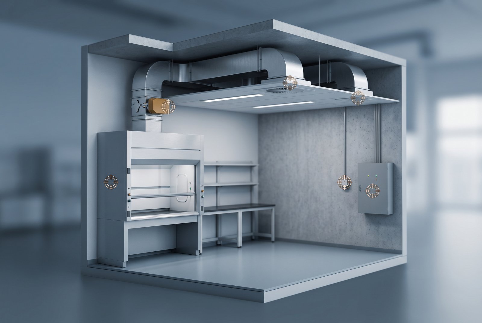
A laboratory ventilation sequence of operation is a written engineering deliverable that answers two questions for each controlled device and each operating mode: what the device shall do during normal operation, and what position it shall move to when a component fails — plus who confirms that response. The phrase “what is a sequence of operation” points to this definition — it is not a description of what the system might do, but a specification of what it shall do, and what shall happen when it cannot do that. The scope is decided by the devices you control (room supply valves, general exhaust valves, cabinet exhaust valves, fans, dampers) and the modes you define (occupied, unoccupied, purge, emergency power).
The Five Blocks of a Sequence
A sequence that can be bid and commissioned contains five blocks. Write them in this order. The table below lists each block, what you write in it, and where the numbers or decisions come from — expressed as the institution or standard that provides the authoritative source. (Virginia Tech DCSM Appendix J)
| Block | What you write in it | Where the number comes from |
|---|---|---|
| Mode definitions | For each mode (occupied, unoccupied, purge, emergency power), you write the airflow target, the trigger that switches to that mode, the duration before the switch takes effect, and what other modes are allowed or prohibited. | Texas A&M University design standard for laboratory control systems provides the occupied/unoccupied dimension and the concept of purge mode where required. |
| Device-by-device normal operation | For each controlled device (e.g., room supply valve V-101), you write the setpoint it shall track, the allowable deviation, and what other devices it shall coordinate with. | Yale University design standard 23 36 00 lists the monitored points that must appear in the control diagram — room supply minimum/maximum airflow, room differential pressure, exhaust-system static pressure, fan status and damper position. |
| Device-by-device failure positions | For each device, you write which of the three named fail positions it shall take on loss of power: fail-open-max, fail-closed-min, or fail-to-last-position (FLP); and you state who confirms that choice. | University of Colorado Anschutz Medical Campus requires a device-by-device failure-position table in the sequence, and Texas A&M defines the three options along with the requirement that the position be maintained without external influence. |
| Alarm points and automatic actions | You write each monitored point that shall generate an alarm, the high or low limit, the delay before the alarm activates, whether the alarm only informs or also triggers an automatic system change, and what that change shall be. | ASHRAE Laboratory Ventilation Design Levels classification document defines failure-mode analysis as the process of identifying all possible failures and evaluating their consequences — the basis for deciding which failures need an alarm versus an automatic action. |
| Acceptance criteria and setpoint adjustment | You write the test that shall be performed to verify each alarm and automatic action works, the pass/fail criteria, the tolerance for field adjustment of setpoints, and who performs the test. | NEBB (National Environmental Balancing Bureau), citing ANSI/ASSP Z9.5-2022, requires that ventilation-cabinet minimum airflow be determined by a risk assessment performed by the laboratory safety officer with the design engineer and certifying authority — a model for who provides the acceptance value. |
Design Values, Field Setpoints and Acceptance Criteria Are Three Different Things
In failure response, a design value, a field-adjustable setpoint, and an acceptance criterion play distinct roles. The design value is what the engineer calculates or selects from a standard; the field setpoint is what the technician dials in during commissioning, within an allowed range; the acceptance criterion is the test limit that proves the system works as specified. Confusing them leads to sequences that cannot be tested or that fail validation because a field-adjustable value was treated as fixed. The table below gives one worked example of each.
| Design value | Field setpoint | Acceptance criterion |
|---|---|---|
| Room differential pressure setpoint of +0.02 in. w.g. relative to the corridor (example). | The actual pressure maintained during occupied mode, adjustable between +0.01 and +0.03 in. w.g. to account for door-opening transients and sensor drift, field-adjustable (example). | The system shall maintain the pressure within ±0.005 in. w.g. of the setpoint for 95% of a 24-hour test period, measured by a calibrated manometer independent of the building automation system (example). |
| Cabinet face-velocity target of 100 fpm (example). | The velocity setpoint stored in the cabinet controller, adjustable between 90 and 110 fpm to accommodate sash-height variations and balancing tolerances, field-adjustable (example). | The face velocity shall not drop below 80 fpm or exceed 120 fpm at any tested sash height, verified with a handheld anemometer at nine points across the opening (example). |
| Minimum exhaust airflow for a VAV cabinet, determined by a risk assessment that considers containment, dilution, and contaminant removal per ASHRAE classification (example). | The low-flow limit programmed into the cabinet controller, adjustable within a range approved by the risk-assessment team (example). | The cabinet shall maintain at least the minimum airflow when the sash is fully closed, and the low-flow alarm shall activate within 2 seconds of the airflow dropping below that limit (example). |
The Standards Behind the Sequence, Named Not Paraphrased
The laboratory ventilation sequence of operation rests on a pedigree of standards that define its scope and requirements. The primary references are ACGIH Industrial Ventilation, ANSI/AIHA/ASSE Z9.5, and ASHRAE Laboratory Design Guide. These documents establish the principles of containment, dilution, airflow tracking, and pressure control that a sequence must implement. You must also be aware of ANSI/ASSP Z9.5-2022, NFPA 45, and ASHRAE Guideline 36 — High-Performance Sequences of Operation for HVAC Systems — but you name them, you do not paraphrase their clause text or cite specific section numbers, because the full text of those standards is not freely available. Your sequence inherits the concepts (e.g., “low-flow alarm is required”) without copying proprietary wording. This naming practice keeps the sequence actionable while respecting copyright boundaries.
Room-Level Control and Cabinet-Level Control: Which Layer Owns Which Failure
Two Controllers, One Room
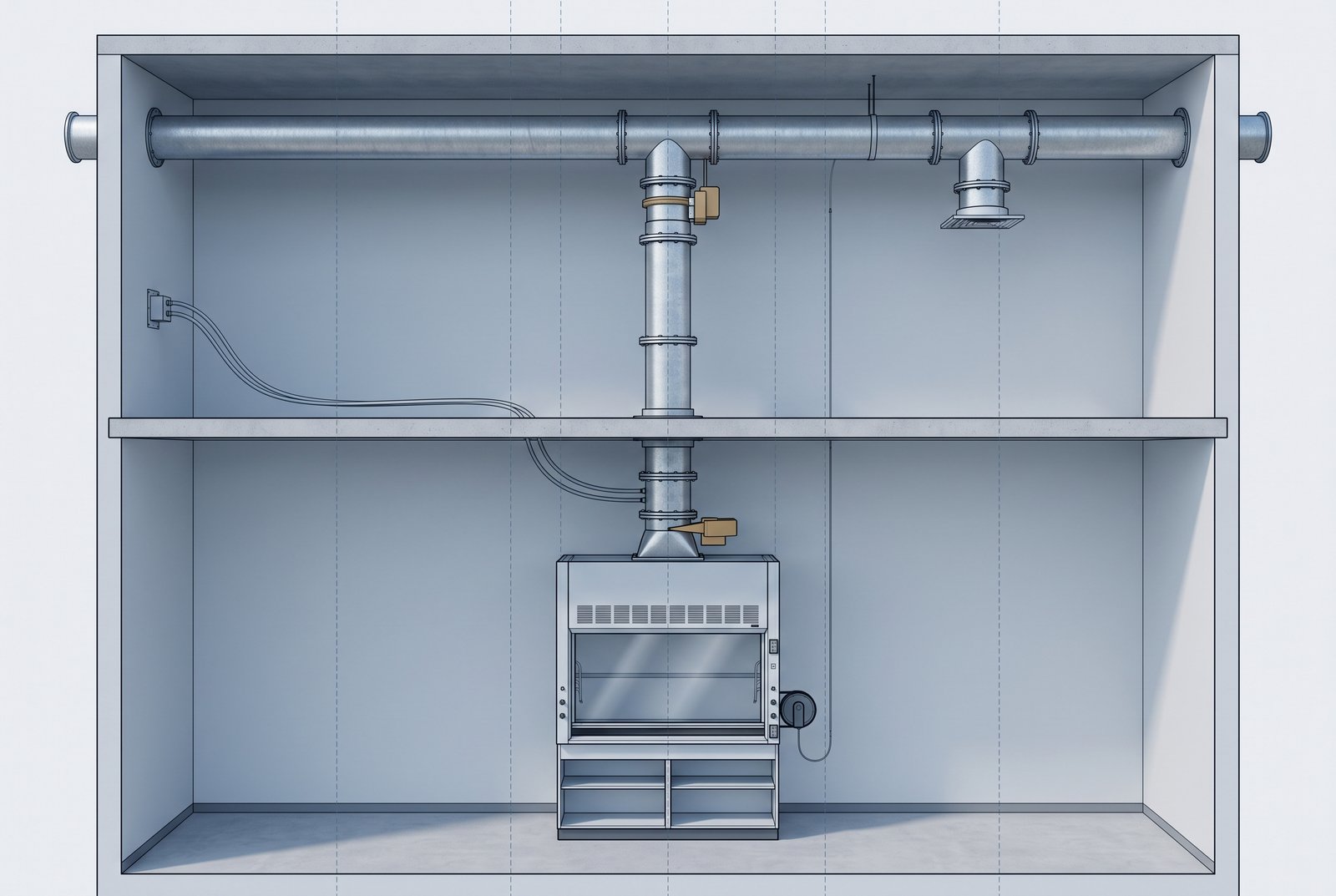
A laboratory with variable-air-volume (VAV) fume hoods has two controllers that share the room: the cabinet-level controller (often built into the hood) and the room-level controller (typically a building automation system terminal). The cabinet controller owns the face-velocity target, the VAV damper position, the fail position of that damper, the face-velocity alarm, and the sash-height signal (the sash is only a signal input — its height requirements belong to the sash height requirements page). The room controller owns supply-and-exhaust airflow tracking, fan-speed control, room differential pressure as a monitored point (the decision of what pressure to maintain belongs to the makeup air and room pressure page), and the optimization objective described in Texas A&M University design standard: the system shall deliver the lowest airflow that still satisfies temperature constraints and maintains the required pressurization relative to adjacent spaces.
The two controllers communicate via an analog or digital signal (e.g., 0-10 VDC or BACnet MS/TP) that tells the room controller how much exhaust the cabinet needs right now.
What the Cabinet Layer Owns
The cabinet layer owns every action and failure that happens inside the fume-hood enclosure. The cabinet controller shall maintain the face-velocity setpoint (example — 100 fpm) by modulating the exhaust damper. It shall calculate the required exhaust airflow from the measured sash height and the face-velocity target. It shall send that airflow demand to the room controller as a real-time signal. On loss of main power, the exhaust damper shall move to one of the three named fail positions defined by Texas A&M: fail-open-maximum (normally open), fail-closed-minimum (normally closed), or fail-to-last-position (FLP) — and that position shall be maintained without external influence (spring return or supercapacitor hold). The cabinet shall alarm if the face velocity drops below the low limit (example — 80 fpm) for more than the allowed delay (example — 2 seconds).
The sash-height signal shall be read as a 0-10 VDC or digital input; the cabinet shall not decide safe sash height — that is the user’s responsibility, defined in the sash height requirements page. (CAV vs VAV fume hoods)
What the Room Layer Owns
The room layer owns the coordination between supply air, general exhaust, and cabinet exhaust, and the consequences of a failure in any of those streams. The room controller shall track the total exhaust airflow (cabinet exhaust plus general exhaust) and shall command the supply airflow to match it, minus any offset required for pressurization. It shall control the exhaust-fan speed (or inlet-guide-vane position) to maintain the duct static-pressure setpoint. It shall monitor the room differential pressure relative to the corridor and shall alarm when the pressure drifts outside the acceptable range defined in the makeup air and room pressure page. Per Texas A&M‘s control-system objective, the room controller shall operate at the lowest airflow that keeps the room within its temperature setpoint band (example — 70-74°F) and maintains the required pressurization direction (positive or negative).
The room layer does not decide the cabinet-level fail position — that is specified in the sequence by the responsible engineer (EoR) following Yale University‘s requirement that senders be fail-safe or fail-in-place and be confirmed by the EoR.
Three Device Sequences, Written Out
These three device sequences are deliverable A1. Each sequence states what the device shall do during normal operation and what it shall do when a component fails, across the four defined modes. The failure positions are grounded in Texas A&M‘s three options (normally open-maximum / normally closed-minimum / last position, maintained without external influence) and Yale‘s directive that the choice be confirmed by the EoR.
Room supply valve (V-101)
- In occupied mode, the valve shall modulate to deliver the airflow commanded by the room controller, which shall be the sum of cabinet exhaust and general exhaust minus the pressurization offset.
- In unoccupied mode, the valve shall modulate to deliver the minimum ventilation airflow (example — determined by risk assessment).
- In purge mode, the valve shall open to its maximum design position to deliver the purge airflow (example — 150% of occupied design).
- On loss of main power, the valve shall move to its spring-return fail position (normally open-maximum or normally closed-minimum as specified by the EoR) and shall hold that position without external influence.
- If the valve position feedback disagrees with the command by more than 10% for longer than 30 seconds, the room controller shall alarm “supply valve mismatch” and may switch to a backup valve if redundant valving is installed.
Room general exhaust valve (V-102)
- In occupied mode, the valve shall modulate to maintain the room differential-pressure setpoint (the value and tolerance belong to the makeup air and room pressure page).
- In unoccupied mode, the valve shall close to its minimum position to deliver only the general exhaust portion of the minimum ventilation airflow.
- In purge mode, the valve shall open to its maximum design position to exhaust the purge airflow.
- On loss of main power, the valve shall move to its spring-return fail position (normally open-maximum or normally closed-minimum as specified by the EoR) and shall hold that position without external influence.
- If the room differential pressure cannot be maintained within tolerance for longer than 60 seconds, the valve shall alarm “pressure control fault” and may lock in its current position if that is the fail-safe direction for the room. (make-up air requirements)
Fume-hood exhaust damper (V-103)
- In occupied mode, the damper shall modulate to maintain the face-velocity setpoint (example — 100 fpm) based on the measured sash height.
- In unoccupied mode, the damper shall close to its minimum airflow position (the minimum shall be set by a risk assessment that considers containment, dilution, and contaminant removal).
- In purge mode, the damper shall open to its maximum design position to exhaust the purge airflow.
- On loss of main power, the damper shall move to its spring-return fail position (normally open-maximum or normally closed-minimum as specified by the EoR) and shall hold that position without external influence; if electronic FLP is selected, a supercapacitor shall provide hold-up power for at least 10 seconds to record the last position before shutdown.
- If the face velocity drops below the low limit (example — 80 fpm) for more than the allowed delay (example — 2 seconds), the cabinet controller shall alarm “low face velocity” and may automatically close the sash if that safety feature is enabled.
Occupied, Unoccupied and Purge: The Modes You Must Define
The Modes You Must Write Down
Three operating modes shall appear in every laboratory ventilation sequence of operation: occupied, unoccupied, and — where required by the safety assessment — purge. A fourth mode, emergency power, may be needed if the laboratory has a backup generator or uninterruptible power supply for critical ventilation. You must write down each mode because the sequence shall behave differently in each: different airflow targets, different fail-safe positions, different alarm thresholds. The modes are not suggestions; they are states the control system shall recognize and transition between based on defined triggers. If you omit a mode definition, the controls contractor cannot price the logic to implement it, and the startup team cannot verify that the system responds correctly when that mode is called.
What Changes Between Occupied and Unoccupied
When the room switches from occupied to unoccupied mode, four things change: the total ventilation airflow target, the cabinet minimum-airflow setpoint, the room pressure-control tolerance, and which alarms are active. Texas A&M University design standard gives an institutional example: 8 air changes per hour (ACH) during occupied periods and 4 ACH during unoccupied periods, with the sash closed — but that specific 8/4 ratio is Texas A&M’s institutional value, not a universal requirement. The decision of what ACH targets to use belongs to the laboratory air changes page. Your sequence shall specify the trigger that initiates the transition. For example: When the occupancy sensor detects no movement for 15 minutes (example, field-adjustable), the room shall transition from occupied to unoccupied mode. The 15-minute delay is field-adjustable (, field-adjustable) because different labs have different chemical-retention characteristics and different schedules. (laboratory air changes per hour)
Purge and Emergency-Power Modes
Purge mode exists to rapidly remove airborne contaminants after a spill or release, or to prepare the room for maintenance. Yale University design standard states that purge mode shall be provided “where required” and shall maintain the required airflow across normal power, emergency power, and smoke-purge conditions. When purge is activated (typically by a dedicated purge button or a building automation system command), the room supply valve and all exhaust valves shall open to their maximum design positions to deliver the purge airflow (example — 150% of occupied design airflow). The fans shall run at full speed, bypassing any static-pressure control loops. The system shall remain in purge mode for a preset duration (example — 30 minutes, field-adjustable) or until manually cancelled. Emergency-power mode engages when normal utility power fails and the backup generator starts.
In this mode, the sequence shall maintain at least the minimum safe ventilation airflow (as determined by risk assessment) using the available emergency-power circuits, which may have lower capacity than normal power.
The Mode Transition Table, Filled
The mode-transition table documents every allowed state change, what triggers it, what changes in the system, and how failure conditions are inherited. A filled table ensures the controls programmer implements the transitions exactly as the sequence requires. Below is a table with five rows, covering the required transitions plus one emergency-power scenario.
| From → To | Trigger | What changes | Failure inheritance |
|---|---|---|---|
| Occupied → Unoccupied | No occupancy detected for 15 minutes (example, field-adjustable). | Total ventilation airflow drops to the unoccupied target (e.g., Texas A&M‘s institutional example of 4 ACH). Cabinet minimum airflow may reduce per risk assessment. Room pressure-control tolerance may widen. | If a device failure occurs during the transition, the device shall remain in its current fail position (open-max, closed-min, or last-position) as specified for the originating mode until the failure is cleared. |
| Unoccupied → Occupied | Occupancy sensor detects movement, or a scheduled occupancy period begins. | Total ventilation airflow increases to the occupied target (e.g., Texas A&M‘s institutional example of 8 ACH). Cabinet minimum airflow returns to its occupied value. Room pressure-control tolerance tightens to the occupied band. | Any failure present in unoccupied mode shall persist into occupied mode; the sequence shall alarm that a failure exists during an occupied period. |
| Any mode → Purge | Purge button pressed, or purge command received from building automation system. | All supply and exhaust valves open to maximum design position. Fan speed controllers override to 100%. All energy-saving algorithms (e.g., supply-exhaust tracking offset) are suspended. | If a valve or fan failure exists when purge is commanded, the system shall attempt to achieve maximum airflow with the remaining functional devices and shall alarm “purge capacity reduced.” |
| Purge → Previous mode | Purge timer expires (example — 30 minutes, field-adjustable), or purge is manually cancelled. | Valves and fans return to the positions required by the mode that was active before purge (occupied or unoccupied). Energy-saving algorithms resume. | A failure that occurred during purge shall be inherited by the returning mode; the sequence shall not automatically reset failures when exiting purge. |
| Normal power → Emergency power | Utility power loss detected, backup generator starts and stabilizes. | Non-critical loads (e.g., general lighting, non-essential receptacles) may be shed. Ventilation system operates on emergency-power circuits, which may have limited capacity — the sequence shall prioritize maintaining minimum safe airflow to all cabinets. | Failures that existed before the power loss shall persist; new failures due to the power transition (e.g., a valve that lost its spring-return power) shall be handled according to their device-specific fail-position specification. |
The table makes explicit what the sequence shall do at each boundary. Without it, the transition logic is left to the controls contractor’s interpretation, which often leads to mismatched expectations and change orders during startup.
Minimum Flow and the Risk Assessment Behind It
There Is No Universal Minimum
No single minimum-airflow value works for every VAV fume hood in every laboratory. The 8 ACH occupied / 4 ACH unoccupied example from Texas A&M University is an institutional target for whole-room ventilation, not a prescription for individual cabinet minimum flow. NEBB, citing ANSI/ASSP Z9.5-2022, states that each VAV cabinet’s minimum airflow shall be determined by a deep risk assessment performed by the laboratory safety officer together with the design engineer and the certifying authority. You cannot copy a value from another project’s sequence, because the chemicals used, the sash-management practices, the room pressure hierarchy, and the consequences of a containment breach differ. The sequence shall state the minimum airflow for each cabinet, expressed as the driving constraint (closed-sash face velocity or dilution airflow) and the basis on which it was set — the number is an outcome of the risk assessment, not a starting point.
The Three Jobs Minimum Flow Must Do
A VAV fume hood’s minimum airflow, when the sash is fully closed, must accomplish three distinct jobs simultaneously. First, it must maintain containment — the inward face velocity (example — 60 fpm) that prevents contaminants from escaping the hood enclosure even when the sash is closed and no one is working at the hood. Second, it must provide sufficient dilution to keep the concentration of any residual contaminants below the exposure limit within the hood’s internal volume. Third, it must ensure contaminant removal — the airflow must transport any released material through the ductwork to the exhaust treatment system or atmosphere. If the minimum flow is too low for any one of these jobs, the hood is not safe in its low-flow state. The sequence shall specify which job drives the minimum for each cabinet (e.g., minimum set by containment requirement of 60 fpm face velocity at closed sash).
(ASHRAE laboratory ventilation design levels)
The Low-Flow Alarm Is a Standard Requirement
ANSI/ASSP Z9.5-2022 requires that every ventilation cabinet be equipped with a flow indicator or airflow sensor that alerts the user when the exhaust airflow drops below a low-limit threshold. The standard does not fix the threshold value; it requires that a threshold exist and that the alert be perceptible to the user. In your sequence, you shall write: The cabinet controller shall monitor the exhaust airflow and shall activate a visual and audible alarm at the hood when the airflow drops below the minimum setpoint for longer than the allowed delay (example — 2 seconds). The alarm is not optional — it is a standard requirement paraphrased from Z9.5. The sequence shall also state where the alarm is annunciated (at the hood, at the room controller, or both) and whether it resets automatically when airflow recovers or requires manual acknowledgment. (NEBB)
How the Number Gets Set, and By Whom
The minimum-airflow value reaches the sequence through a concrete four-step process, not through a signature on a form. First, the controls contractor shall measure the as-built performance of each hood with the sash fully closed, recording the actual airflow achieved at the controller’s minimum-position command (example — the airflow measured when the damper is at its minimum commanded position). Second, the balancing contractor shall verify that the measured airflow matches the design minimum within the tolerance specified in the sequence (example — ±10%). Third, the laboratory safety officer shall review the measured performance against the risk assessment that considers the worst-case chemical stored or used in that hood, the hood’s containment performance at that airflow, and the consequences of a failure.
Fourth, the safety officer, the design engineer, and the certifying authority shall agree on one of three outcomes: accept the measured value as the minimum, require a higher minimum to meet the risk assessment, or require modifications to the hood or controls to achieve a lower minimum that still satisfies containment, dilution, and contaminant-removal needs. The sequence shall record the agreed value and the date of the agreement — not who signed, but what was measured and why that number was chosen.
Fail Positions: Fail-Safe, Fail-in-Place and Fail-to-Last-Position
Three Legal Actuator Fail Positions
Texas A&M University design standard names three positions that a VAV-box actuator may take when main power is lost: normally open-maximum (fail-open-max), normally closed-minimum (fail-closed-min), and fail-to-last-position (FLP). All three are legal because each serves a different safety objective. Fail-open-max ensures maximum exhaust airflow continues during a power outage, protecting against containment loss. Fail-closed-min ensures minimum exhaust airflow continues, protecting against room over-depressurization. FLP maintains the last commanded position, protecting against disturbance to sensitive experiments. The standard adds that the chosen position shall be “maintained constantly without external influence” — meaning once the actuator moves to its fail position, it must stay there without needing continuous power or external force. Your sequence shall specify one of these three for each device; you cannot write “fail-safe” without saying which position that is. (Texas A&M laboratory control systems)
Hazard Direction Picks the Position
The decision rule for exhaust-side devices is stated in mechanism terms, not energy preference. For a fume-hood exhaust damper, the fail direction is chosen by two factors: the containment requirement (which way does the hazard move if containment is lost?) and the room-pressure hierarchy (is this room positive or negative relative to adjacent spaces?). If the primary hazard is a toxic vapor that must stay inside the hood, the damper shall fail open-max to maintain maximum exhaust and containment. If the primary hazard is that the room could become dangerously negative and pull contaminants from neighboring labs, the damper shall fail closed-min to preserve the room’s pressure boundary. If the experiment inside the hood is oxygen-sensitive or vibration-sensitive, and any airflow change could ruin it, the damper shall fail-to-last-position. The rule “fail-closed for energy waste” is deleted from this logic — energy saving is a normal-operation concern, not a fail-safe criterion.
Spring-Return vs Fail-to-Last-Position Actuators
A spring-return actuator is a mechanical device: when power is removed, a spring forces the valve or damper to a predetermined position — either normally closed (NC) or normally open (NO). It has no third option. The position is held by the spring’s mechanical force, which requires no external power once the initial movement is complete. An electronic fail-to-last-position (FLP) actuator uses stored energy — typically a supercapacitor — to remember the last commanded position and hold the device there after power loss. The supercapacitor provides hold-up power for a defined duration (example — 10 seconds) while the position is recorded; after that, the actuator may gradually drift if the mechanical load exceeds the holding torque. Spring-return is simpler and always works; FLP offers more flexibility but depends on stored energy that can deplete over time. Your sequence shall state which type each device uses, because the controls contractor cannot price the correct hardware without knowing whether a supercapacitor circuit is needed.
The Fail-Position Matrix, Filled
The fail-position matrix is deliverable A2. It lists every controlled device, the hazard direction that governs its fail position, the actuator type, the specific fail position, how that position is held, and who confirms the choice. Each cell is filled; where a value is project-specific, it is labelled “(example)”. The matrix ensures the sequence is unambiguous about failure response.
| Device | Hazard direction | Actuator type | Fail position | Holding condition | Confirmed by |
|---|---|---|---|---|---|
| Room supply valve V-101 | Room over-pressurization could force contaminants into corridor. | Spring-return (NC) | Fail-closed-min | Spring force maintains closed position without external power. | Responsible engineer (EoR) per Yale University requirement. |
| Room general exhaust valve V-102 | Room under-depressurization could pull contaminants from adjacent labs. | Spring-return (NO) | Fail-open-max | Spring force maintains open position without external power. | Responsible engineer (EoR) per Yale University requirement. |
| Fume-hood exhaust damper V-103 (toxic lab) | Toxic vapor must stay contained inside hood. | Spring-return (NO) | Fail-open-max | Spring force maintains open position without external power. | Laboratory safety officer + responsible engineer (EoR). |
| Fume-hood exhaust damper V-104 (flammable lab) | Room under-depressurization could pull flammable vapors through building walls. | Spring-return (NC) | Fail-closed-min | Spring force maintains closed position without external power. | Laboratory safety officer + responsible engineer (EoR). |
| Fume-hood exhaust damper V-105 (sensitive experiment) | Airflow change could disturb micro-balance or cell culture. | Electronic FLP | Fail-to-last-position | Supercapacitor provides 10-second hold-up, then mechanical brake (example). | Principal investigator + responsible engineer (EoR). |
| Supply fan VFD | Loss of supply airflow could cause room to go negative. | Electronic FLP | Fail-to-last-position | Supercapacitor maintains last speed command for 30 seconds (example), then coasts down. | Responsible engineer (EoR) + facility electrician. |
| Exhaust fan VFD | Loss of exhaust could cause room to go positive and push contaminants out. | Electronic FLP | Fail-to-last-position | Supercapacitor maintains last speed command for 30 seconds (example), then coasts down. | Responsible engineer (EoR) + facility electrician. |
| Room pressure relief damper | Room over-pressurization could damage door seals or windows. | Spring-return (NO) | Fail-open-max | Spring force maintains open position without external power. | Responsible engineer (EoR). |
| Chemical storage room exhaust damper | Accumulation of flammable or toxic vapors in storage room. | Spring-return (NO) | Fail-open-max | Spring force maintains open position without external power. | Laboratory safety officer + responsible engineer (EoR). |
| Emergency power transfer switch | Loss of ventilation during power outage could allow hazard buildup. | Mechanical interlock | Fail-to-emergency-source | Mechanical latch holds position without power. | Facility electrician + responsible engineer (EoR). |
The matrix makes explicit what each device shall do when power fails. Without it, the fail-safe direction is left to the controls contractor’s guess, which often leads to mismatched hardware and change orders during installation.
Alarm Points and Automatic Actions Are Not the Same Thing
Two Different Jobs on One Point List
Every monitored point in a laboratory ventilation sequence has one of two jobs: alarm (announce that something is out of range) or action (automatically change the system to bring it back into range). An alarm tells a person; an action changes a device. Merging the two jobs onto the same point creates two failure modes. First, nuisance shutdowns: if every alarm also triggers an immediate system change, transient fluctuations (like a door opening or a sash being adjusted) cause unnecessary equipment cycling, which wears out actuators and confuses operators. Second, silent loss: if every system change happens without an alarm, a failure can persist for hours or days before anyone notices — the system automatically compensates until it can compensate no longer, then fails catastrophically. Your sequence shall separate the two jobs explicitly: for each point, you shall write whether it only alarms, only acts, or alarms first then acts after a defined delay.
The Points That Only Announce
Three points shall only announce — they shall not trigger any automatic system change, because the appropriate response depends on human judgment and context. First, low hood flow (below the minimum setpoint) is a standard requirement paraphrased from ANSI/ASSP Z9.5-2022: the cabinet controller shall alert the user when exhaust airflow drops below the low limit, but it shall not automatically close the sash or switch to another hood unless that specific action has been approved by the laboratory safety officer. Second, room pressure drift (the differential pressure moves outside the tolerance band defined in the makeup air and room pressure page) shall alarm at the building automation system workstation, but the sequence shall not automatically adjust supply or exhaust valves to correct it — the drift may indicate a door left open, a filter change in progress, or a balancing error that requires investigation.
Third, supply-air temperature fluctuation (outside the setpoint band, example — ±2°F) shall alarm at the mechanical-room controller, but the sequence shall not automatically switch heating/cooling sources because the fluctuation may be intentional during mode transitions or emergency-power operation.
The Points That Trigger an Action
Three points shall trigger an automatic action — they shall change the system state without waiting for human intervention, because the consequence of delay is immediate hazard. First, loss of containment (face velocity drops below the containment threshold, example — 60 fpm) shall automatically close the sash to the safe height (if motorized sash control is installed) and may activate a local strobe to warn users away from the hood. Second, face-velocity excursion above the high limit (example — 150 fpm) shall automatically reduce the exhaust damper position to bring the velocity back into range, because excessive velocity can disturb sensitive experiments and waste energy. Third, critical component failure (e.g., exhaust-fan status changes from “running” to “stopped” while the room is in occupied mode) shall automatically start the standby fan (if redundancy is provided) and shall switch the room to purge mode if the failure cannot be corrected within a defined time window (example — 30 seconds).
These actions happen automatically because waiting for a person to respond would allow the hazard to escalate.
The Alarm-and-Action Table, Filled
The alarm-and-action escalation table is deliverable A4. It lists each point that generates an alarm or triggers an action, the limit direction, the specific action (if any), the delay before the action occurs, and the escalation path if the first action does not resolve the condition. Every cell is filled; delay values are worked examples labelled “(example)”.
| Point | Limit direction | Action | Delay (example) | Escalation path |
|---|---|---|---|---|
| Cabinet face velocity | Below containment threshold (example — 60 fpm) | Close sash to safe height (if motorized); activate local strobe. | 2 seconds | 1) Local strobe at hood → 2) BAS alarm to operator → 3) Automatic sash closure → 4) EHS notification if not acknowledged in 5 minutes. |
| Cabinet exhaust airflow | Below low-flow setpoint | None (alarm only) — alert user at hood. | 2 seconds | 1) Visual/audible alarm at hood → 2) BAS alarm to operator → 3) Laboratory safety officer notification if not acknowledged in 10 minutes. |
| Room differential pressure | Outside tolerance band (positive or negative) | None (alarm only) — alert operator at BAS workstation. | 30 seconds | 1) BAS alarm to operator → 2) Text alert to facility technician → 3) Escalate to on-call engineer if not acknowledged in 15 minutes. |
| Exhaust-fan status | Changes from “running” to “stopped” during occupied mode | Start standby fan (if redundant); if no standby, switch room to purge mode. | 5 seconds | 1) Start standby fan → 2) BAS alarm to operator → 3) Switch to purge mode if standby also fails → 4) EHS notification + evacuate room if purge cannot be maintained. |
| Supply-air temperature | Outside setpoint band (example — ±2°F) | None (alarm only) — alert mechanical-room operator. | 60 seconds | 1) Mechanical-room controller alarm → 2) BAS alarm to operator → 3) Escalate to HVAC technician if not corrected in 30 minutes. |
| General exhaust valve position | Disagrees with command by >10% for sustained period | Lock valve in current position; activate “valve mismatch” alarm. | 30 seconds | 1) “Valve mismatch” alarm → 2) Lock valve position → 3) Switch to backup valve if available → 4) Notify controls contractor for repair. |
| Emergency power transfer | Fails to transfer to generator on utility loss | Shed non-critical loads; attempt second transfer. | 10 seconds | 1) Shed non-critical loads → 2) Second transfer attempt → 3) BAS alarm to operator → 4) Notify facility electrician + EHS. |
| Purge mode active | Exceeds maximum allowed duration (example — 60 minutes) | Automatically cancel purge; return to previous mode. | 60 minutes | 1) Warning at 45 minutes → 2) Automatic cancellation at 60 minutes → 3) BAS alarm “purge overtime” → 4) Log event for safety review. |
The table makes explicit what each point shall do and in what order. Without it, the controls programmer implements a default “alarm-and-act-immediately” for every point, which leads to either nuisance shutdowns or silent loss of containment. (AIHA Synergist)
What to Do When Laboratory Ventilation Fails
The First Two Minutes, Ordered
When a laboratory ventilation component fails, the system shall execute this sequence in the first two minutes, in numbered order:
- Sense — The affected controller shall detect the out-of-range condition (e.g., face-velocity sensor reads 0 fpm, exhaust-fan status changes from “running” to “stopped”, room differential pressure drifts outside tolerance).
- Verify (debounce delay) — The controller shall wait for a verification period (example — 2 seconds for face-velocity loss, 5 seconds for fan-status change, 30 seconds for pressure drift) to distinguish a genuine failure from a transient fluctuation like a door opening or sash adjustment.
- Switch to backup — If a redundant component is available and the failure persists through the verification period, the controller shall automatically switch to the backup (e.g., start the standby fan, open the backup supply valve, transfer to emergency-power circuit).
- Annunciate — Simultaneously with step 3, the controller shall activate the appropriate alarm (visual/audible at the hood, BAS alarm to the operator, text alert to the facility technician) stating which component failed and what automatic action was taken.
- Fail-over verification — The controller shall verify that the backup component is operating correctly (e.g., standby-fan status returns to “running”, room pressure returns to tolerance) within a defined window (example — 30 seconds). If the backup also fails, the system shall escalate to the next response level (e.g., switch room to purge mode, notify EHS).
The sequence shall be written in this exact order because swapping steps (e.g., alarming before verification) causes nuisance alarms, and delaying the switch to backup risks loss of containment.
Consequences Depend on the Architecture
The consequence of a fan or damper failure is a function of the exhaust-system architecture — whether the lab uses independent (dedicated) exhaust ducts or a common (manifolded) system. In an independent-exhaust architecture, a fan failure affects only the single cabinet or room served by that fan; the remaining cabinets continue to operate. In a common-manifold architecture, a single fan failure can affect every cabinet on that manifold, potentially shutting down ventilation for multiple labs simultaneously. NIH Prudent Practices notes that this architectural choice determines the severity of a failure and the redundancy required. The decision between independent and common architecture belongs to the laboratory exhaust manifold page; your sequence shall reference that page for the architecture decision, then describe how the sequence responds given the chosen architecture (e.g., If the lab uses a common manifold per the laboratory exhaust manifold page, a fan failure shall trigger purge mode for all cabinets on that manifold).
(fume hood exhaust fan sizing) (NIH Prudent Practices)
The Human Side: What Operators Must Know
Operating personnel shall be trained on four items grounded in NIH Prudent Practices. First, the power-loss procedure: if utility power fails and the emergency generator does not start within the transfer-time window (example — 10 seconds), operators shall manually initiate the building-wide emergency ventilation protocol, which may involve opening windows or activating portable exhaust units. Second, label meanings: every alarm annunciator, purge button, and mode-selector switch shall have a label that states what it does (Purge — opens all valves to maximum for 30 minutes) and what not to do (“Do not cancel purge during chemical-release response”). Third, misuse consequences: operators shall understand that overriding a fail-safe position (e.g., manually forcing a spring-return valve open when it should fail closed) can compromise containment or room-pressure control. Fourth, response coordination: when an automatic action occurs (e.g., standby fan starts), operators shall follow the posted checklist to verify the action succeeded and document why the primary component failed.
Event Tracking and Change Management
Every failure response shall be logged in a response-event record that includes: the date/time, the component that failed, the automatic action taken, the verification result, the personnel notified, and the time to restore normal operation. I2SL Smart Labs LVMP Coordinator program requires this log to support three management functions. First, trend analysis: repeated failures of the same component type (e.g., face-velocity sensors drifting out of calibration every six months) trigger a preventive-maintenance review. Second, change-management loop: if a failure reveals that the sequence’s automatic action is inadequate (e.g., the standby fan also fails too often), the sequence shall be revised, and the revision shall be tracked through a change-control form that records what was changed, why, who approved it, and when it takes effect. Third, training updates: the event log feeds back into operator training, ensuring that the next time a similar failure occurs, operators have seen the previous response and know what to expect.
The sequence shall specify where the event log is kept (e.g., building automation system historian, laboratory safety-management software) and who reviews it (e.g., monthly by the laboratory safety officer).
The Monitoring Points Your Control Diagram Must Show
The Point List Is the Sequence, Drawn
The point list in a laboratory ventilation sequence is not a supplementary appendix — it is the sequence itself, expressed as the set of physical measurements the control diagram shall show. Yale University design standard 23 36 00 enumerates the points that must appear: face velocity, sash open area, cabinet exhaust flow, room supply minimum and maximum airflow, room general exhaust minimum and maximum airflow, supply temperature, room temperature, room humidity, room differential pressure, exhaust-system static pressure, fan status and damper position, stack velocity, and terminal supply/exhaust minimum and maximum airflow. Each point answers one of the sequence’s core questions: How much air is moving? Is it moving in the right direction? Is the component that moves it working? The control diagram draws these points with their normal ranges; the sequence writes what shall happen when a point leaves that range.
Room Points and Cabinet Points
Points are divided by layer. Cabinet-layer points belong to the fume-hood controller: face velocity (example — 100 fpm target, 80–120 fpm normal range), sash open area (calculated from sash-height sensor), and cabinet exhaust flow (the airflow demanded by the hood). Room-layer points belong to the building automation system: room supply minimum/maximum airflow (the bounds within which the supply valve shall modulate), room general exhaust minimum/maximum airflow (the bounds for the general exhaust valve), supply temperature (example — 55°F ±2°F), room temperature (example — 72°F ±2°F), room humidity (example — 40–60% RH), room differential pressure (the value and tolerance belong to the makeup air and room pressure page), exhaust-system static pressure (the signal that controls fan speed), fan status (running/stopped), damper position (0–100% open), and stack velocity (the velocity at the discharge point).
Each layer’s controller shall monitor its own points; the two controllers shall exchange the points they need (e.g., cabinet exhaust flow is sent to the room controller for supply-exhaust tracking).
The Monitoring-Point Table, Filled
The monitoring-point table is deliverable A3. It lists at least twelve points from the Yale-enumerated set, states which layer owns each, its normal role or range, what type of alarm it generates (if any), what automatic action it triggers (if any), and who sets the value. Every cell is filled; project-specific values are labelled “(example)”. (laboratory exhaust manifold)
| Point | Layer (room/cabinet) | Normal role/range | Alarm type | Automatic action | Set by |
|---|---|---|---|---|---|
| Face velocity | Cabinet | 100 fpm target, 80–120 fpm normal range (example). | Low-limit (below 80 fpm) and high-limit (above 120 fpm). | Below low limit: close sash to safe height (if motorized). High limit: reduce damper position. | Laboratory safety officer based on containment risk assessment. |
| Sash open area | Cabinet | Calculated from 0–100% sash-height sensor. | None (monitoring only). | None — sash position is user-controlled. | Manufacturer (sensor calibration). |
| Cabinet exhaust flow | Cabinet | Actual exhaust airflow (example — 150–800 cfm). | Low-limit (below minimum setpoint). | None (alarm only) — alert user at hood. | Balancing contractor (measured during commissioning). |
| Room supply minimum airflow | Room | Lower bound for supply-valve modulation (example — 200 cfm). | Low-limit (below minimum for >30 seconds). | None (alarm only) — alert operator. | Design engineer (based on occupancy and risk assessment). |
| Room supply maximum airflow | Room | Upper bound for supply-valve modulation (example — 1200 cfm). | High-limit (above maximum for >30 seconds). | None (alarm only) — alert operator. | Design engineer (based on duct and fan capacity). |
| Room general exhaust minimum airflow | Room | Lower bound for general-exhaust-valve modulation (example — 100 cfm). | Low-limit (below minimum for >30 seconds). | None (alarm only) — alert operator. | Design engineer (based on dilution requirements). |
| Room general exhaust maximum airflow | Room | Upper bound for general-exhaust-valve modulation (example — 600 cfm). | High-limit (above maximum for >30 seconds). | None (alarm only) — alert operator. | Design engineer (based on duct and fan capacity). |
| Supply temperature | Room | 55°F ±2°F (example). | High/low limit (outside ±2°F). | None (alarm only) — alert mechanical-room operator. | Mechanical engineer (based on dew-point and room-load calculation). |
| Room temperature | Room | 72°F ±2°F (example). | High/low limit (outside ±2°F). | None (alarm only) — alert operator. | Facility standard (set by occupant comfort policy). |
| Room humidity | Room | 40–60% RH (example). | High/low limit (outside 40–60% RH). | None (alarm only) — alert operator. | Facility standard (set by material-sensitivity requirements). |
| Room differential pressure | Room | Setpoint and tolerance from the makeup air and room pressure page. | High/low limit (outside tolerance). | None (alarm only) — alert operator. | Determined on the makeup air and room pressure page (make-up-air page). |
| Exhaust-system static pressure | Room | Setpoint for fan-speed control (example — 1.0 in. w.g.). | Low-limit (below setpoint –0.2 in. w.g.) indicates fan failure. | Start standby fan (if redundant). | Balancing contractor (adjusted during fan-curve verification). |
| Fan status | Room | Running/stopped. | Status change from “running” to “stopped” during occupied mode. | Start standby fan; if no standby, switch room to purge. | Controls contractor (wired to fan starter). |
| Damper position | Room | 0–100% open. | Position disagrees with command by >10% for >30 seconds. | Lock damper in current position; activate “position mismatch” alarm. | Controls contractor (actuator calibration). |
| Stack velocity | Room | Minimum safe discharge velocity (example — 3000 fpm). | Low-limit (below minimum for >60 seconds). | None (alarm only) — alert EHS. | Design engineer (based on plume-rise and re-entrainment risk). |
What the Diagram Leaves Out
A control diagram shows points and connections, but it cannot show three critical elements that belong in the written sequence. First, alarm delays: the diagram cannot indicate that a low face-velocity alarm shall wait 2 seconds before activating, to debounce transient sash movements. Second, interlocks: the diagram cannot show that the purge button shall be disabled (grayed out) when the room is already in purge mode, or that emergency-power mode shall lock out non-critical loads automatically. Third, software logic: the diagram cannot express that the room controller shall calculate the total exhaust airflow every 500 milliseconds, compare it to the supply airflow minus the pressurization offset, and command the supply valve to match within a 5% tolerance. These three elements — delays, interlocks, and calculation loops — must appear in the sequence’s text, because they define how the drawn points actually behave in time and under failure conditions.
The Laboratory Ventilation Sequence of Operation Package: What to Hand Your Controls Contractor
The Five-Part Package
The laboratory ventilation sequence of operation you hand your controls contractor is a five-part package. First, the mode definitions — occupied, unoccupied, purge, emergency-power — each with its airflow target, trigger, and duration. Second, the device-by-device fail positions — for each valve, damper, and fan, which of the three Texas A&M options (normally open-maximum, normally closed-minimum, last position) it shall take on loss of power. Third, the alarm-and-action split — which points only announce, which trigger an automatic change, and the escalation path if the first change does not resolve the condition. Fourth, the acceptance criteria — the test that shall be performed to verify each alarm and action works, the pass/fail limit, and who performs the test. Fifth, the change-management record — a log of every failure response and sequence revision, with the date, what changed, why, and who approved it. These five parts together make the sequence bid-able, programmable, and verifiable.
The Open Items That Still Need a Ruling
Three items in the sequence remain open — they cannot be closed by the design engineer alone, because they require a ruling from the owner’s responsible engineer (EoR), the laboratory safety officer, or the authority having jurisdiction (AHJ). First, the exhaust-system architecture choice (independent vs common manifold) determines the consequence of a fan failure; that choice belongs to the laboratory exhaust manifold page, and the sequence shall reference that page. Second, the room differential-pressure setpoint and tolerance — the value and allowable drift — come from the makeup air and room pressure page (make-up-air page). Third, the minimum airflow for each VAV cabinet is set by a risk assessment performed by the laboratory safety officer with the design engineer and certifying authority; the sequence shall record the agreed value and the date of agreement, not who signed. These three open items are explicitly called out in the sequence with a placeholder “TBD — ruling required from EoR/LSO/AHJ” so the controls contractor knows they are not missing data.
The One-Page Fail-Position Template, Filled
The one-page fail-position template is deliverable A5. It lists every controlled device, the mode it is in when power fails, the fail position it shall take, what alarm activates, and what automatic action follows. The template is filled with worked examples; it is the sheet you attach to the sequence when you send it for EoR confirmation.
| Device | Mode | Fail position | Alarm | Action |
|---|---|---|---|---|
| Room supply valve V-101 | Occupied | Fail-closed-min (spring-return NC). | “Supply valve fail-closed” at BAS workstation. | None — valve position is already at fail position. |
| Room general exhaust valve V-102 | Occupied | Fail-open-max (spring-return NO). | “General exhaust fail-open” at BAS workstation. | None — valve position is already at fail position. |
| Fume-hood exhaust damper V-103 (toxic lab) | Occupied | Fail-open-max (spring-return NO). | “Cabinet exhaust fail-open” at hood + BAS. | None — damper position is already at fail position. |
| Fume-hood exhaust damper V-104 (flammable lab) | Occupied | Fail-closed-min (spring-return NC). | “Cabinet exhaust fail-closed” at hood + BAS. | Close sash to safe height (if motorized) to maintain containment. |
| Fume-hood exhaust damper V-105 (sensitive experiment) | Occupied | Fail-to-last-position (electronic FLP). | “Cabinet exhaust FLP active” at hood. | Supercapacitor holds last position for 10 seconds, then mechanical brake engages. |
| Supply fan VFD | Any | Fail-to-last-position (electronic FLP). | “Supply fan FLP active” at mechanical room. | Supercapacitor holds last speed command for 30 seconds, then coasts down. |
| Exhaust fan VFD | Any | Fail-to-last-position (electronic FLP). | “Exhaust fan FLP active” at mechanical room. | Supercapacitor holds last speed command for 30 seconds, then coasts down. |
| Room pressure relief damper | Any | Fail-open-max (spring-return NO). | “Pressure relief fail-open” at BAS workstation. | None — damper position is already at fail position. |
The Verification Pass Before You Send It
Before you send the sequence to the controls contractor, run these five acceptance tests — deliverable A6 — grounded in the ASHRAE principle that failure modes are established at commissioning. Each test is an executable sentence with a pass criterion and who does it.
- Face-velocity containment test — With the sash fully open, command the cabinet exhaust damper to its minimum position; measure the face velocity at nine points across the opening. Pass: all nine readings ≥80 fpm. Performed by: balancing contractor.
- Room pressure boundary test — Close all doors and windows; command the supply valve to its minimum position and the general exhaust valve to its maximum position; measure the room differential pressure relative to the corridor. Pass: pressure stays within the tolerance band defined in the makeup air and room pressure page for 5 minutes. Performed by: controls contractor.
- Fail-position spring-return test — Remove power from the room supply valve actuator; observe the valve movement. Pass: valve moves to its specified fail position (closed for NC, open for NO) within 2 seconds and holds without external power. Performed by: controls contractor.
- Alarm debounce delay test — Simulate a transient low face-velocity event (quick sash movement) lasting 1 second; monitor the alarm activation. Pass: alarm does not activate (2-second debounce delay works). Performed by: controls contractor.
- Backup-fan start test — While the room is in occupied mode, simulate a primary-exhaust-fan failure (status changes from “running” to “stopped”); monitor the standby-fan start. Pass: standby fan starts within 5 seconds and room pressure returns to tolerance within 30 seconds. Performed by: controls contractor.
These five tests verify that the sequence’s written behavior matches the physical system’s actual response. (fume hood inspection checklist) Next step — email the five-part package + one-page template + these test steps to your project’s responsible engineer (EoR) with the question: Does this package capture every device, mode, fail position, and verification step you need to confirm before the bid?
A laboratory ventilation sequence of operation built this way is not a description of intent: it is a bid-ready, testable specification.
Leave a Reply