




Key Takeaways
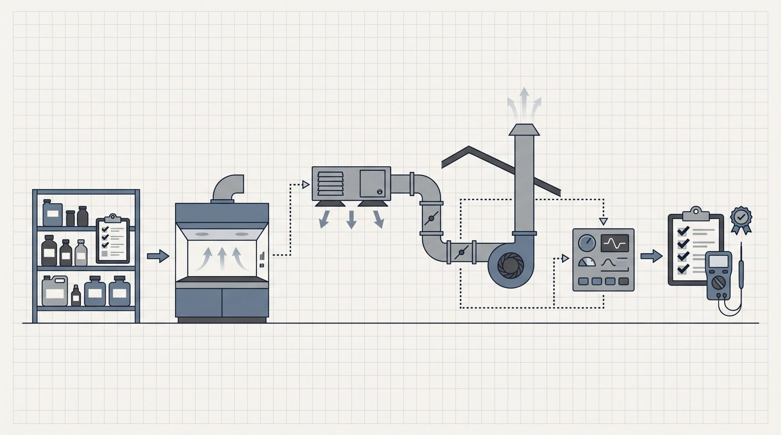
- Laboratory exhaust system design is a decision sequence, not a single calculation. — Laboratory exhaust system design is the ordered set of project decisions that runs from the chemical inventory through local exhaust, makeup air and room pressure, duct and fan transport, stack discharge, controls, and acceptance, and it exists to produce a system that protects occupants and discharges effluent safely.
- Start with the chemical inventory. — OSHA’s laboratory standard, 29 CFR 1910.1450, requires a written Chemical Hygiene Plan, which makes the hazard list the legal and technical starting point for every later decision.
- Air changes per hour are a symptom, not a design basis. — NFPA 45’s annex note states that design based only on air changes per hour is not considered correct design; supply volume follows the greater of the cooling load, the hood exhaust, and the equipment exhaust.
- No recirculation, no re-entrainment. — Laboratories run on 100% outside air, and stacks are commonly sized to clear the roofline (about 10 ft) at high discharge velocity (about 3000 fpm) in institutional standards, not in federal law.
- Know who owns each decision. — OSHA’s guidance expects local exhaust and on-site ventilation systems to be designed by someone experienced in that work, while the owner and EHS set the hazard and pressure targets.
Laboratory exhaust system design is the ordered set of decisions — hazard inventory, local exhaust, makeup air and room pressure, duct and fan transport, stack discharge, controls, and acceptance — that turns a chemical inventory into a ventilation system protecting occupants and discharging effluent safely. If you are asking how to design a laboratory ventilation system, no single calculation settles it: what settles it is the order in which the decisions get made and the specialist each one is handed to. The order runs module by module, so a facility planner, EHS lead, or design engineer can sequence a whole-laboratory project and know where each detailed task belongs.
Which Regulations and Standards Shape Laboratory Exhaust System Design?
OSHA 1910.1450 and the Chemical Hygiene Plan
OSHA’s laboratory standard, 29 CFR 1910.1450, requires covered employers to establish a written Chemical Hygiene Plan that names the engineering controls and sets criteria for selecting ventilation. That plan is where the chemical list lives, and the chemical list is the first design input for any exhaust system.
OSHA’s compliance guidance for the standard reaches into ventilation specifics: laboratory air should be exhausted directly, not recirculated, and a negative pressure differential should exist between the laboratory and adjacent non-laboratory spaces so chemical vapors do not migrate outward. Read as a design instruction, the rule demands a hazard list and a pressure direction before anyone sizes a fan. A team that starts with an equipment order has to reverse-engineer both later, after supply and exhaust values are already fixed.
NFPA 45 and the No-Recirculation Rule
NFPA 45 requires laboratory ventilation systems to keep hazardous chemical vapors from recirculating, and it states that hood and local exhaust discharge must not be returned to the occupied space. Its scope covers chemical hoods, local exhaust hoods, fume arms, special local exhaust, and other exhaust systems, which places local exhaust inside the standard, not beside it.
The practical consequence is that no return-air strategy serves the hazard path. Once-through airflow becomes the working assumption for the whole project, and every later decision — makeup air volume, duct routing, stack sizing, control strategy — is built on that assumption instead of being renegotiated room by room.
Institutional Standards: Z9.5, NIH, Stanford, UT — Guidance, Not Law
Above the code floor sit institutional standards that supply the numbers a project team budgets against. ANSI/ASSP Z9.5-2022 is the U.S. laboratory ventilation standard covering the fundamentals that govern design and operation. NIH’s Design Requirements Manual, Stanford’s laboratory standard and design guidelines, and the University of Tampa’s ventilation standard each add requirements for supply air, pressure relationships, and stack discharge.
The distinction decides how you cite those requirements. A stack height of 10 ft above the adjacent roofline, a discharge velocity of 3000 fpm, and a makeup-air floor at 95% of exhaust volume come from institutional standards, not federal regulation. Name the institution when quoting a value like that, and confirm which standard your owner and authority having jurisdiction enforce.
| Source | What it is | How to use it in a project |
|---|---|---|
| OSHA 29 CFR 1910.1450 | Federal laboratory standard; requires the Chemical Hygiene Plan and states ventilation expectations in its compliance guidance | Sets the legal floor: hazard list, no recirculation, negative pressure direction |
| NFPA 45 | Fire-safety standard for laboratories; prohibits recirculation of hazardous vapors; scope includes hoods, local exhaust, and fume arms | Rules out return-air strategies on the hazard path |
| ANSI/ASSP Z9.5-2022 | Laboratory ventilation design and operation standard, cited here by name and scope | Confirm whether the owner or authority having jurisdiction adopts it |
| Institutional standards (NIH, Stanford, University of Tampa) | Owner-level design requirements with specific values | Source of the numbers you budget: supply, pressure, stack height, velocity |
Decide first: name the standards your project must satisfy before the inventory starts, because that choice determines which numbers the later steps are allowed to use.
Start With a Hazard Inventory Before Any Laboratory Exhaust System Design Work
If you are planning how to design a laboratory ventilation system for a new building or a major renovation, the sequence starts one step earlier than most teams expect: with the chemical and operations inventory.
Build the Chemical and Operations Inventory First
The inventory is the design input, not a compliance formality. For every room, list the chemicals, typical quantities per session, the operations that can release them (extraction, distillation, digestion, weighing, dispensing), and who works there. University programs collect this with a chemical-use questionnaire that feeds a control-banding tier; Clemson University’s laboratory ventilation design standard, for example, asks about the chemical mix, quantities, frequency, and acute hazards before it assigns a ventilation category.
Hazard class then drives local exhaust type, airflow, and the pressure target. A room handling trace amounts of weak acids and a room running solvent distillation do not converge on the same system, and no fan selection sheet can repair that difference once the inventory is skipped.
Arrange Controls: Engineering Before Administrative Before PPE
OSHA’s hierarchy of controls ranks engineering controls first, then administrative controls, then work practices, and finally PPE. Ventilation is an engineering control because it physically separates the person from the hazard instead of relying on behavior.
The budget consequence follows directly. A project that substitutes procedures for ventilation places the residual risk on the most changeable part of the system, the people. When the inventory shows acute, high-volume, or high-toxicity hazards, the engineering-control line in the budget comes before the signage, training, and PPE lines.
Who Runs the Inventory and Who Sets the Targets
The owner and EHS define the hazard list and the exposure targets; the engineer converts those targets into a system. OSHA’s guidance for the laboratory standard states that local exhaust and on-site ventilation systems should be designed only by someone experienced in that work — an engineer or industrial hygienist.
Write that split into the project plan in week one. If no one in the owner’s organization can state the pressure target and the hazard categories, the equipment vendor will set them by default, and a supplier should not own a safety decision that the standard assigns to experienced design judgment. The inventory itself is an EHS task run with the researchers who handle the materials, because the people performing the operations know the quantities, the durations, and the failure modes better than any purchasing record does.
Your next step: run the inventory for one floor before any hood order; the list determines every airflow number that follows.
Match Local Exhaust to the Hazard: Hoods, Source Capture, and Equipment Exhaust
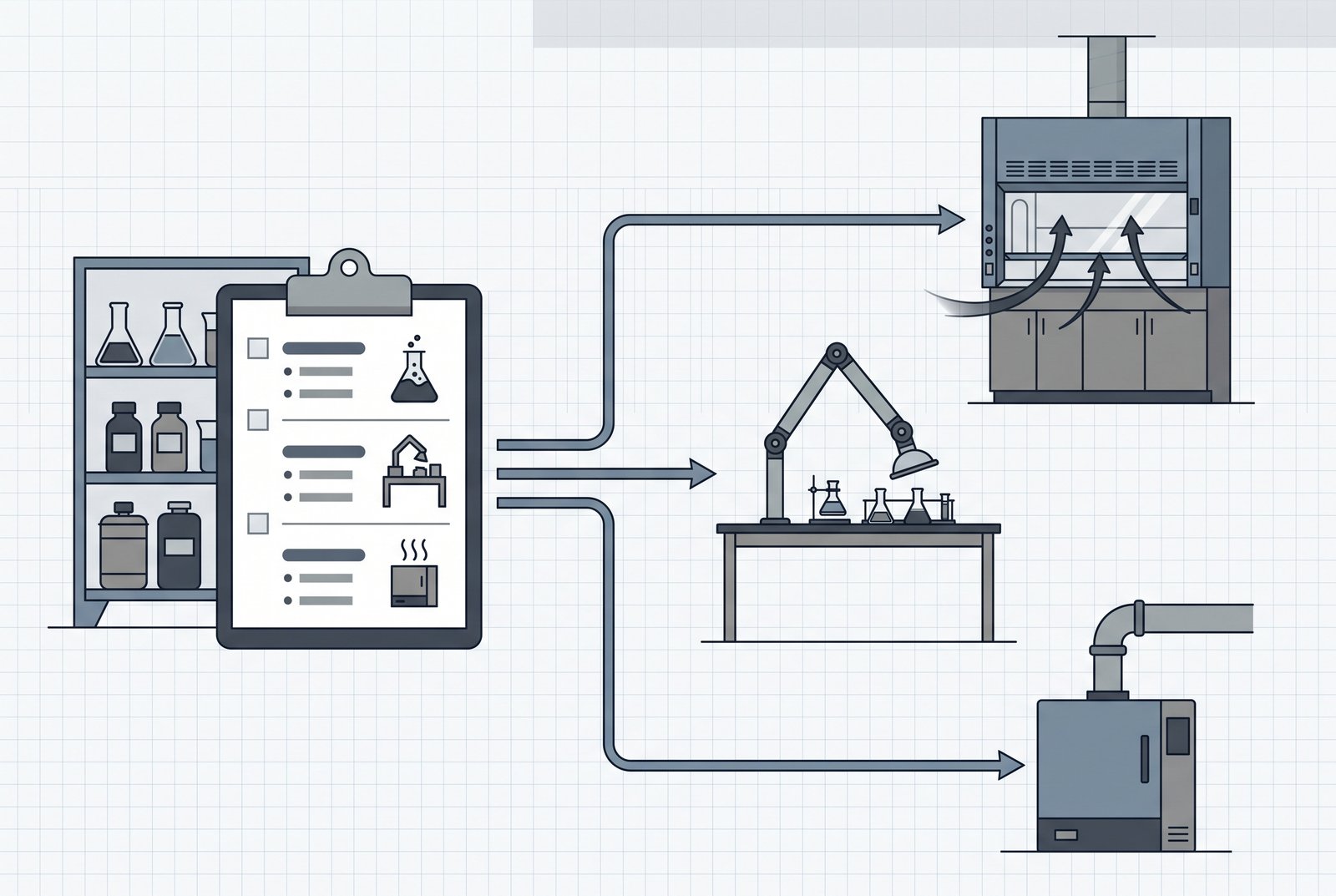
Fume Hoods Are the Primary Protection — Choose a Type
OSHA’s compliance guidance for the laboratory standard names the chemical fume hood as the most important element in protecting laboratory personnel; when the hazard is airborne, the hood is the first engineering control to specify. Hood class — ducted general purpose, bypass, ductless, or specialty — follows from the chemistry. Our guide to the types of fume hoods walks the five-step selection.
At project level you decide the hood count and class per room, not the catalog number. Two hoods in a teaching lab and six hoods in a research bay produce different makeup-air, diversity, and stack consequences, and those consequences get locked in before the model is chosen.
Source Capture: Fume Arms and Point Exhaust Are Engineer-Designed Local Exhaust
Source capture means collecting contaminants close to where they are generated: fume arms, slot hoods, canopies, and instrument exhaust. NFPA 45’s scope explicitly includes fume arms and special local exhaust systems alongside chemical hoods, so they belong to the regulated system, not to the accessories list. Capture performance depends on distance, cross-drafts, and generation rate, which is why OSHA’s guidance states that local exhaust and on-site systems should be designed by someone experienced in that work.
This step is a design responsibility, not a product category. Sizing an extraction arm is a separate specialization with its own equipment market; inside this project sequence, source capture is one option the engineer evaluates against a hood when the operation is stationary, the release point is fixed, and the capture distance stays short.
Equipment and Instrumentation Exhaust Belongs in the Same Inventory
Vacuum ovens, acid digestion blocks, gas chromatographs, solvent evaporators, and biological safety cabinets all move air. Their exhaust volumes belong on the same list as hood flows, because makeup air and stack sizing add them together.
Equipment exhaust discovered after the fan schedule is fixed forces either a fan change or an operating restriction. Both options cost money and schedule; adding the items during the inventory costs nothing.
Quantity the Airflow Per Hood — the CFM Calculation Is the Owner’s Job
Hood airflow comes from face velocity multiplied by open sash area, with corrections for sash position, bypass, and the connected duct system. That arithmetic belongs to our fume hood airflow calculation guide, which walks the calculation for a single hood. The project role here is to record hood count and class, then hand the calculation to that step.
Product handoff stays conditional. A general purpose steel fume hood is a candidate when the hazard route calls for ducted, once-through exhaust. A ductless fume hood is a candidate only where the route is low-volume, low-toxicity, and filtration-only exhaust satisfies the standard that applies to your site. Neither is a default answer for a laboratory with a real chemical inventory.
| Hazard pattern from the inventory | Local exhaust option to evaluate | Where the detail lives |
|---|---|---|
| Routine solvent work at a bench, moderate volumes | Ducted fume hood at the bench | Hood class selection |
| Fixed release point, short capture distance, stationary task | Source-capture arm, slot hood, or canopy | Engineer’s local exhaust design |
| Heat, vapor, or aerosol released by equipment instead of an open bench | Dedicated equipment exhaust | Same inventory and airflow list |
| Trace weighing, low toxicity, filtration acceptable under the enforced standard | Ductless hood as a conditional candidate | Standard check first, then product review |
You now have a local exhaust list per room — hood classes, counts, capture options, and equipment exhaust — ready for the airflow and makeup-air steps.
Balance Makeup Air and Room Pressure — and Leave ACH Out of the Design Basis
Rooms Stay Negative: Pressure Direction and Why
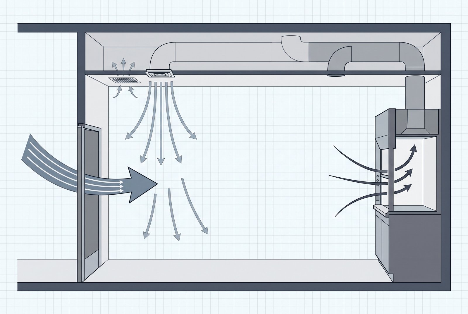
A laboratory should sit at a lower pressure than the corridors around it, so air moves into the lab instead of out of it. OSHA’s compliance guidance calls for a negative pressure differential between the laboratory and adjacent non-laboratory spaces, and Stanford’s design guidelines require lab spaces to be mechanically supplied and exhausted, with exhaust that never returns to the building.
Decide direction first, magnitude later. Single-room balancing — the supply offset, the measured pressure difference, and the interlock behavior — is the specialist task covered in our page on fume hood makeup air requirements. A project-level plan fixes the direction and names who verifies it; it does not re-derive the room-by-room balance.
Supply Air: 100% Outside Air, No Recirculation, Opposite-Side Diffusers
Once-through outside air is the working assumption for laboratories because NFPA 45 forbids recirculating hazardous vapors and university design guidelines match it: Stanford requires 100% outside air, mechanical supply and exhaust, and no return path to the building.
Layout follows the same logic. Stanford also asks that supply enter on the side opposite the hoods so the room sweep moves air toward the hood face, and NFPA 45 addresses supply diffuser location and warns against placements that degrade hood performance. A diffuser blowing straight at a hood face reduces capture by pushing air out of the opening.
How Much Makeup Air? Institutional Rules of Thumb
The University of Tampa’s ventilation standard requires replacement air of at least 95% of the laboratory exhaust volume, with the small remainder drawn from adjacent spaces, and it forbids makeup air pulled back from other laboratory areas. The same standard caps room air velocity at the hood face at one-half of face velocity, with one-third preferred, roughly 50 fpm at six feet in typical hoods.
NFPA 45’s annex expresses the same concern in different units: keep room air velocity near the hood as low as feasible, ideally below 30% of face velocity. Two institutions, two measurement styles, one design goal. Use the limit your own enforced standard requires, not the version that flatters your airflow budget.
Why Air Changes per Hour Is Not a Design Basis (and Where It Still Shows Up)
NFPA 45’s annex note states that design based only on air changes per hour is not considered correct design. Laboratories in use commonly run above 6 ACH and idle labs can drop to 4 ACH, and the actual supply volume is set by the greater of the cooling load, the hood exhaust, and the equipment exhaust.
Clemson University reaches the same conclusion through control banding: ventilation categories are assigned from a hazard questionnaire, not from a blanket ACH number. ACH still has a place — early space conversations, rough imbalance checks, energy planning — but it is not the input that sizes a system. If a proposal quotes only “8 air changes,” ask which hood flow and equipment load that number was built on.
Decide the pressure direction and the makeup basis now; before you set a control strategy, make sure ACH has left the design numbers.
Transport the Exhaust: Duct Runs and Fan Selection in Laboratory Exhaust System Design
Duct Design Belongs to a Specialist — What You Decide at Project Level
Duct sizing, material selection, velocity limits, branch entry, and condensate drainage belong to the duct design task covered in our page on fume hood duct sizing. At the project level you decide the routing logic: which hoods share a run, whether hazardous exhaust gets its own shaft, and where ducts may cross occupied space.
Routing logic is the expensive half of this step. A run shared between incompatible exhaust streams, or a duct strung through a return plenum, shows up later as a field change that the airflow tables never predicted. Settle the logic before the specialist runs the arithmetic: routing choices made during planning cost drawings, and the same choices revisited during installation cost schedule as well.
Fan Selection and Redundancy — Who Specs the Operating Point
The fan’s operating point — static pressure and flow at the design condition — is the province of the fume hood exhaust fan sizing guide. Your project decision at this level is the redundancy policy: what the system does when a fan stops, whether that is a standby unit, an N+1 set, or a manifolded bank with a spare.
Redundancy touches two later steps. A manifolded system needs minimum-velocity logic under part load, which the control step must carry forward with the stack velocity in mind, and its restart behavior gets verified at commissioning. Decide the policy early, because it changes the electrical and mechanical space budget.
Don’t Mix Hazardous and General Exhaust Unless Engineered
NFPA 45 requires hazardous vapors not to be recirculated, and its scope covers the local-exhaust systems this step transports. Published design guidance treats hazardous exhaust as a dedicated chase, not a shared shaft with general exhaust, and several state mechanical codes classify laboratory exhaust streams by hazard for this reason.
What may share a run is an engineering call that depends on the chemical classes, the locally enforced code, and fire-separation requirements. Get the classification wrong and the problem migrates to the stack, where cross-contamination turns into re-entrainment and then into a failed acceptance test. Record the classification and its basis in the basis-of-design document, so the acceptance step tests the system that the classification produced.
Decide the routing and redundancy policy now; you can hand the sizing arithmetic to the duct and fan owners in the next work session.
Stack Discharge and Re-Entrainment: The Last 10 Feet of Laboratory Exhaust System Design
Why Stack Height and Discharge Velocity Matter
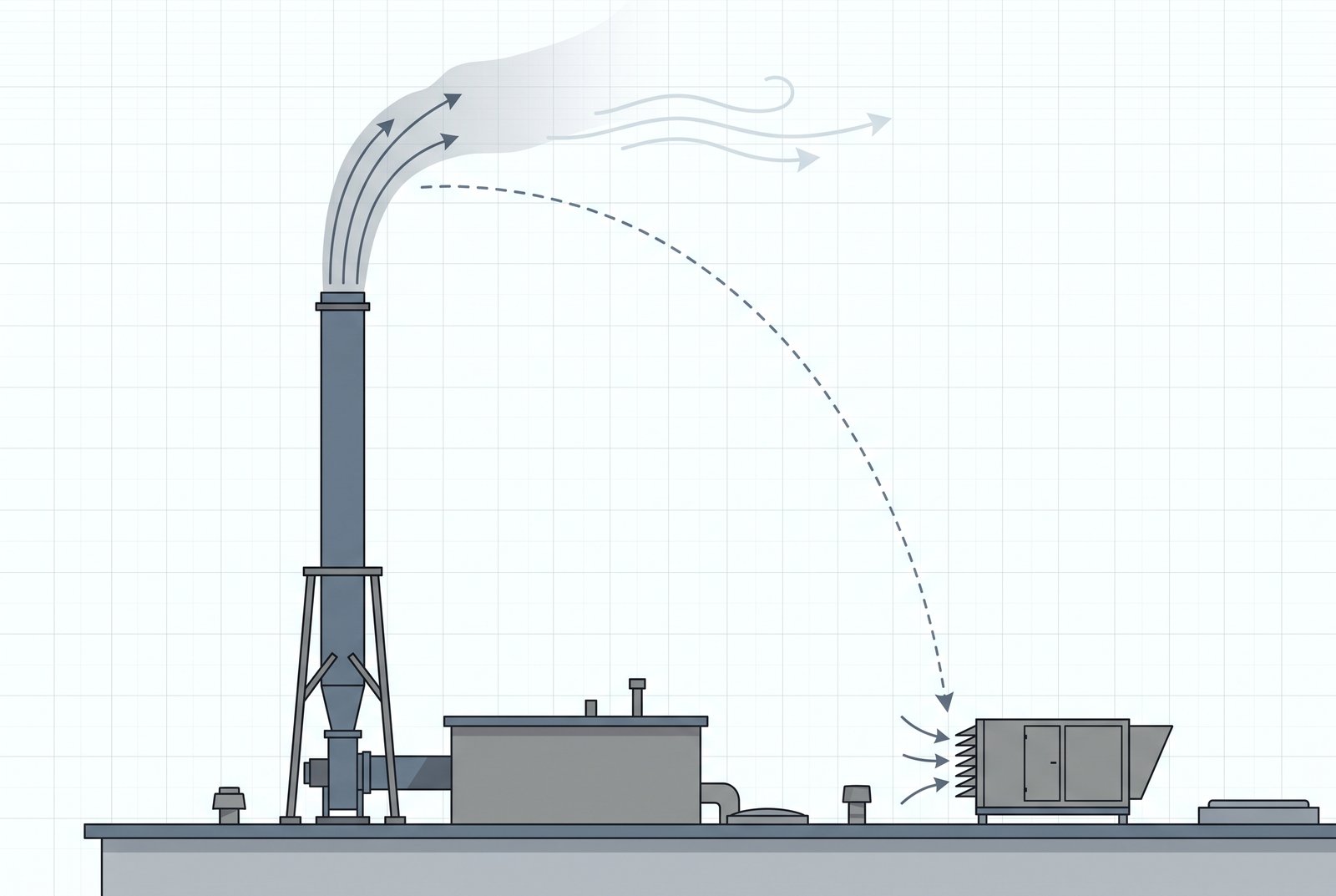
Exhaust leaving a roof enters the wind field around the building, and when the plume stays inside the envelope of recirculating air, some of it comes back. NIH’s Design Requirements Manual requires exhaust design to account for stack height and discharge velocity so the plume clears the building’s boundary layer, and it describes stacks generally at least 3 m (about 10 ft) above the roofline and nearby roof structures.
University standards attach numbers to the same idea. The University of Tampa’s ventilation standard requires discharge vertically upward, at least 10 ft above the adjacent roofline, with an exit velocity of at least 3000 fpm to reduce re-entrainment. Those are institutional design benchmarks: quote them with the institution attached and confirm what your authority having jurisdiction requires.
Re-Entrainment: How Contaminated Air Comes Back Into Intakes
Re-entrainment is the return of exhaust into a building intake, a window, or a rooftop unit. Height buys separation from the low-speed air near the roof, and velocity buys plume rise and dilution. The two work together: a tall stack with weak discharge can still carry contamination back into an intake when the wind drops.
Variable-volume systems create a specific trap. When hoods close and total flow drops, stack velocity drops with it, and the plume loses the momentum that kept it away from intakes. NIH’s DRM addresses this by requiring means such as bypass to maintain minimum stack discharge velocity under variable flow — a control provision made for a stack reason, which the control step must carry. The plume is weakest when the building is quietest, and that is also when laboratory work is least supervised.
Verifying Discharge Performance — ASHRAE 110 Belongs to the Acceptance Owner
Discharge and hood containment are verified, not assumed. The acceptance step measures face velocity, runs airflow visualization, and uses tracer gas when the hazard profile calls for it; ANSI/ASHRAE 110 is the recognized containment test protocol that institutional standards reference.
The protocol itself — test setup, tracer gas method, pass criteria — belongs to the acceptance owner and appears in the commissioning step. This step only fixes the expectation: stack and hood performance are testable deliverables with a scheduled verification. State that expectation in the design documents, so the acceptance scope is defined before construction instead of being negotiated after it.
Select the stack height and exit velocity targets now; the speed that keeps the plume clean becomes a control requirement in the next step.
Choose the Controls: CAV, VAV and Minimum Stack Velocity
CAV vs VAV: Airflow-Differential and Space-Pressure Control
Constant air volume keeps the exhaust flow fixed at the design value; variable air volume lets it follow sash position or demand. VAV systems are typically built on one of two control approaches: airflow-differential control, which compares measured supply and exhaust and trims the difference, or space-pressure control, which holds a measured room pressure against a setpoint. Consulting white papers describe both routes for laboratory facilities.
The choice turns on what must stay constant. If room pressure is the binding constraint, pressure control simplifies the loop. If hood capture is the constraint, airflow tracking with a stack-velocity floor matters more. Keep the stack requirement in view during the comparison: the same variable flow that saves energy can sink the plume at low load.
| Question | CAV | VAV |
|---|---|---|
| Hood flow | Fixed at design, always | Tracks sash position or demand |
| Room pressure | Easy to hold at one condition | Needs pressure or airflow-differential control |
| Stack velocity | Stable, easy to keep above minimum | Can fall at low load — needs bypass or minimum flow |
| Part-load energy | Highest, always at design flow | Lower when hoods are closed |
| Adding a hood later | Rebalances the whole system | Absorbed if capacity was left in the design |
Keep Minimum Stack Velocity Under VAV
NIH’s DRM notes that variable-volume systems need means such as bypass to maintain minimum stack discharge velocity, so contaminants are not entrained into the fresh-air system at low flow. That sentence is the bridge between the stack step and the controls step: the discharge target from the previous decision becomes a control-sequence requirement here.
The cost of omitting it is conditional safety. The system passes at design conditions, when hoods are open, and fails exactly when the plume is weakest, at night and on weekends. Bypass or minimum-flow logic belongs in the sequence before the fan curves are frozen.
Room Pressure Controls and Who Owns Them
Valve selection, pressure sensing, and the full control sequence belong to our page on CAV vs VAV for fume hoods, which covers both control approaches and the sensing options. At project level you decide which variable is held constant and who verifies it at acceptance.
Controls are where the earlier decisions converge: hood demand from the local exhaust step, makeup air from the pressure step, and stack minimum from the discharge step. A sequence that does not carry all three forward fails at commissioning, so write the three requirements into the control specification now.
Choose the control strategy with the stack minimum written into it; the acceptance step will test exactly that sequence.
Commission and Accept: Prove It Works Before Occupancy
When Acceptance Testing Happens
Acceptance is scheduled, not improvised. The University of Tampa’s ventilation standard requires newly installed or modified hoods to be evaluated after installation and before use, then re-tested at least annually and after any major change to the system or the space it serves.
Put those dates in the project plan: pre-occupancy verification, a baseline record, the annual re-test, and a trigger for re-testing after any airflow change — a new hood added to the same run, a control-sequence revision, or a room reconfiguration.
Timing carries commercial weight too: a project that accepts occupancy before verification has already surrendered the easiest moment to require fixes, and every correction afterwards competes with live research and teaching schedules.
What Acceptance Covers — and Whose Checklist It Is
Verification covers face velocity, airflow visualization, and tracer gas testing when the hazard profile calls for it; ANSI/ASHRAE 110 is the containment test protocol that institutional standards reference. The room-to-sign-off checklist — location, installation, and documentation — belongs to our fume hood installation requirements page, and the test method and reporting belong to the ASHRAE 110 fume hood test page.
The Hub-level decision is scope: which hoods, which rooms, and which systems get tested, and who signs the result. A project that tests hoods but never checks the pressure relationship or the stack discharge has verified components while leaving the system unproven. Test records should also state the conditions each result was taken under — sash height, system mode, control setpoint — because a number without conditions cannot be compared with next year’s result.
Commissioning Is a Project-Phase Commitment
Commissioning spans design intent, installation, and operation. Institutional standards carry a commissioning section, and life-cycle approaches treat design, installation, and operation as one sequence instead of three separate handoffs.
The budget and schedule consequence is concrete: commissioning requires the design intent to be written down early — target pressure, minimum stack velocity, assumed diversity — because nobody can verify a target that was never stated. Reconstructing design intent after construction means paying twice for the same answer. The commissioning agent tests whether the written intent was delivered, which requires the intent to exist in a document the agent can quote.
Your next step: write down what each verification must prove before occupancy, and name the person who signs it.
Assign Responsibility: Who Owns Each Laboratory Exhaust System Design Decision
Owner and EHS Set Hazard and Pressure Targets; Engineers Design the System
OSHA’s guidance for the laboratory standard states that local exhaust and on-site ventilation systems should be designed only by someone experienced in that work — an engineer or industrial hygienist. The hazard inventory and the exposure targets come from the owner and EHS, and consulting white papers make the same split for pressure relationships: the owner defines the target, and the designer builds to it.
That line of authority has a practical effect. Whoever pays for the system names the safety criteria, and whoever designs it documents the trade-offs against those criteria. When the two roles blur, the criteria go undocumented and the acceptance step can hold no one accountable.
| Decision | Owner |
|---|---|
| Hazard inventory and exposure targets | Owner / EHS |
| Pressure direction and target | Owner / EHS, verified by the engineer |
| Local exhaust type per hazard | Engineer, with EHS confirmation |
| Hood airflow calculation | Engineer (single-hood calculation page) |
| Duct routing and sizing detail | Engineer (duct sizing page) |
| Fan selection and redundancy policy | Project team with the engineer |
| Stack height and velocity targets | Engineer, against the enforced standard and AHJ |
| Control strategy and sequence | Engineer / controls designer |
| Acceptance scope and sign-off | Owner, EHS, and commissioning agent |
Vendors Advise; They Don’t Set Safety Requirements
A supplier can state a hood’s containment performance and airflow range, but a supplier should not decide which hazard route your laboratory requires. Product selection follows the inventory, and route classification belongs to the design team.
Procurement discipline follows directly: write the hazard route and the governing standard into the specification before the request for quote goes out. Bids then compare like for like, and the safety decision stays where the standards put it.
The Action Checklist: From Inventory to Acceptance
Ten actions in order: inventory the chemicals and operations; set the pressure direction and targets; choose local exhaust per hazard; hand the airflow calculation to the specialist; fix makeup air and supply layout; route the exhaust and set redundancy; set stack height and discharge velocity; choose the control strategy with a stack minimum; schedule acceptance; and name the signer for each step.
The list is the deliverable. It turns one regulation, several standards, and eight specialist tasks into a project order with names attached — exactly what a facility planner needs to carry into the project.
You now have the responsibility map; run each row past the checklist before the first purchase order goes out.
Worked Example: A Teaching Lab With Organic Solvents
The Setup: Rooms, Chemicals, Occupancy
Scenario, used only to demonstrate the sequence: a university is fitting out two teaching laboratories and one preparation room. Operations are liquid-liquid extraction, rotary evaporation, and simple distillation with organic solvents. Classes run six hours a day, four days a week. The teaching assumptions — two fume hoods per laboratory (four total), one vacuum oven in the preparation room, and about 2,000 sq ft per teaching room — are example parameters you replace with your own numbers.
What the inventory produces for this example: a per-room chemical list, quantities per session, operation types, and occupancy. The values matter less than the order: the inventory is complete before any airflow figure is discussed.
Run the Decision Chain and Read the Outputs
Working down the chain, the inventory points to hooded operations as the dominant release path, so the local-exhaust list is four ducted, once-through hoods, with per-hood airflow handed to the airflow-calculation specialist who works from the site’s accepted face velocity and open sash area. Makeup air targets at least 95% of exhaust volume per the University of Tampa institutional standard, with the balance drawn from the corridor and the room held negative to it, and supply diffusers placed opposite the hoods.
The transport step gives the teaching rooms separate exhaust runs with the fan and duct owners doing the sizing, and the redundancy policy is a standby fan so a failure does not cancel a class. Stack targets follow the institutional benchmark: at least 10 ft above the adjacent roofline, discharge vertically, at least 3000 fpm at the outlet. Controls use VAV with minimum-flow logic so stack velocity holds when the hoods close overnight. Acceptance is scheduled before first occupancy, plus an annual re-test.
| Step | What the team decides | Who owns the detail |
|---|---|---|
| Inventory | Chemical and operations list per room | Owner / EHS |
| Local exhaust | Four ducted hoods plus oven exhaust | Engineer; hood type page |
| Hood airflow | CFM per hood from face velocity × sash | Airflow calculation page |
| Makeup air | At least 95% of exhaust, room negative | Makeup air page |
| Transport | Separate runs, standby fan | Duct and fan pages |
| Stack | At least 10 ft, vertical, 3000 fpm | Institutional benchmark plus AHJ |
| Controls | VAV with stack minimum | CAV/VAV page |
| Acceptance | Pre-occupancy plus annual | Installation and ASHRAE 110 pages |
Read the outputs this way: the team leaves the step with a decision order, an owner for every row, and a list of parameters still to compute — hood CFM, room supply offset, duct size, fan static pressure, stack height — each assigned to a named specialist page.
What Changes If the Hazard Profile Changes
Swap the solvents for perchloric acid work: the hood class changes, duct material requirements change, and washdown or dedicated-run provisions get evaluated on the specialist pages. Add a second simultaneous class block to the same room: diversity enters the load calculation, because NIH’s Design Requirements Manual calls for diversity and usage factors so the plant is not sized to a worst-case instant.
The teaching example is the orderly case — known hazards, scheduled occupancy, stable hood counts. Research floors differ, but the sequence holds: the inventory still comes first, and every later step still consumes its output. Changing the input changes the numbers, not the order.
You can run this sequence on your own rooms before committing the first hood order; the order is the deliverable, and the numbers follow it.
Laboratory Ventilation Questions You’ll Still Have (FAQ)
How much makeup air does a fume hood actually need?
The general rule is that supply air must replace what the hoods and equipment exhaust, the room must stay negative to adjacent spaces, and makeup air must not be drawn back from other laboratory areas. One university standard sets the floor at 95% of the exhaust volume.
The exact figure for your hood depends on its airflow, the room’s leakage, and the control strategy. That calculation and the room-by-room balance belong to the makeup air requirements page, not to a project-level estimate.
How often should fume hoods and lab ventilation be re-tested?
The University of Tampa standard sets the sequence: evaluation after installation or modification and before use, then at least annually, and again after any major change to the hood or the ventilation system.
ANSI/ASHRAE 110 is the containment protocol that the test detail draws on. Annual re-testing is institutional practice, not a single federal interval, and the method and reporting live on the ASHRAE 110 test page.
What is a venturi valve — and do I need one?
A venturi valve is a pressure-independent airflow control device: it holds a flow setpoint as duct pressure changes, which matters in VAV laboratory systems where supply and exhaust must track each other and room pressure must stay stable.
Whether you need one follows from the control strategy and the pressure tolerance — the decision covered on the CAV vs VAV page. Match the valve’s flow range to the hood demand range, and keep pressure-sensing points where maintenance can reach them. Add it to the specification only after the strategy is chosen, not before.
Does ANSI/ASSP Z9.5 apply to my lab?
Z9.5-2022 is the U.S. laboratory ventilation standard covering the fundamentals that govern design and operation. Many institutional standards and commissioning references cite it, and a U.S. laboratory project should at least confirm whether the owner or authority having jurisdiction adopts it.
Z9.5 is cited by name and scope only: the full text is a purchased standard, so the numbers here come from OSHA, NFPA 45, and published institutional requirements. Ask the owner’s safety office which edition applies and whether any other laboratory ventilation standard is adopted alongside it.
Decide which of these questions your project needs answered, and send each one to the page that owns it.
The Next Step: Assemble Your Project Team and Order of Work
Start With the Inventory — and Name the Owner for Each Step
Laboratory exhaust system design is a sequence — inventory, local exhaust, makeup air and pressure, transport, stack, controls, acceptance — and the sequence is complete only when every step has a name attached. Three first actions: finish the hazard inventory; assign an owner to each row of the table below; and confirm which standard your authority having jurisdiction enforces.
Sequencing discipline pays late in the project. Teams that order hoods before the inventory re-open the design twice, once for makeup air and once for the stack, and both re-opens move cost and schedule in the same direction.
| Stage | Page to read | What it answers |
|---|---|---|
| Hood selection | types of fume hoods | which hood class fits the operation |
| Airflow per hood | fume hood airflow calculation | how much air each hood needs |
| Makeup air and pressure | fume hood makeup air requirements | supply, offsets, room balancing |
| Duct transport | fume hood duct sizing | material, size, routing limits |
| Fan selection | fume hood exhaust fan sizing | operating point and redundancy |
| Controls | CAV vs VAV for fume hoods | control strategy and sequence |
| Installation and acceptance | fume hood installation requirements | room-to-sign-off checklist |
| Containment testing | ASHRAE 110 fume hood test | test method and reporting |
When You Match a Hazard Route, the Hood Page Takes Over
Product handoff arrives at the end of the sequence, where it belongs. When the inventory points to a ducted, once-through hazard route, a general purpose steel fume hood may be the right class of product to review. When the route is low-volume, low-hazard, and filtration-only exhaust is acceptable to the enforced standard, a ductless fume hood is a candidate. Both are conditional answers, not defaults, and the product pages for those classes take over only after the route and the governing standard are fixed.
The project order is what has to be right, with every decision placed with the specialist who owns it. Start the inventory this week, put a name next to every row, and let the specialized pages carry the arithmetic.
Your next step: start the inventory this week; laboratory exhaust system design begins the day the chemical list is written, not the day the hood arrives.
Leave a Reply