




Key Takeaways
- A laboratory exhaust manifold is a single duct and fan group shared by two or more hoods or labs. — It is an architecture decision, not a duct material choice; settle the layer first, then size the duct.
- Compatibility is a hard gate, not a preference. — Shared streams must stay below their lower explosive limit and must not form explosive compounds.
- Some services leave your table. — Perchloric acid, radioisotope, BSL-3 and BSL-4 work, and select agent work, each follow their own rules.
- Redundancy answers two different questions. — One framework asks how big the system is, the other asks how critical it is; use both, in that order.
- The architecture decides stack count, plume quality and how many rooms lose pressure control at once. — It does not decide duct diameter or fan operating point.
Laboratory Exhaust Manifold: The Shared-or-Dedicated Decision
The Answer in Brief
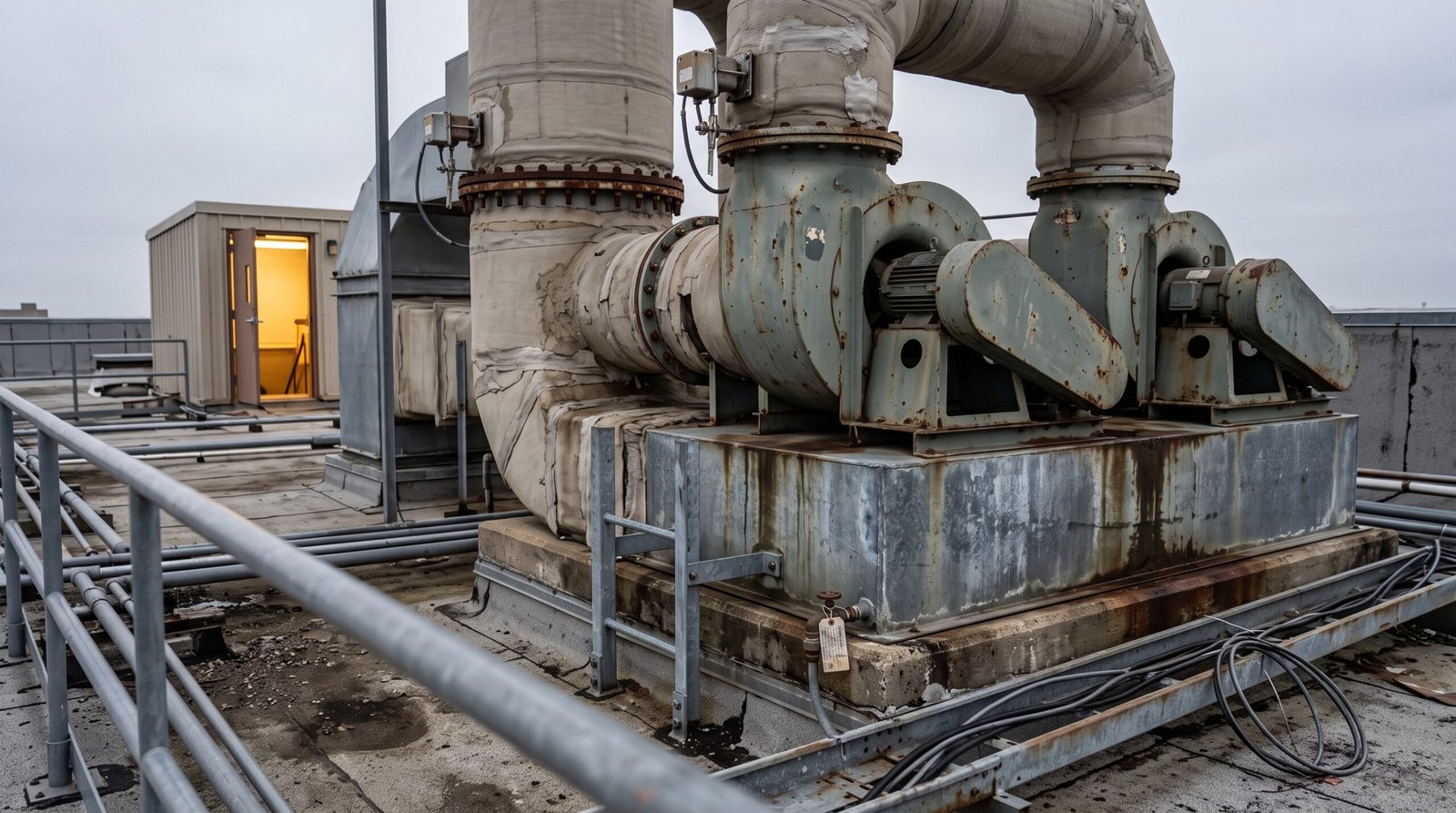
A laboratory exhaust manifold is a single duct and fan group that carries the exhaust from two or more fume hoods or two or more laboratories. It is permitted whenever the combined streams stay compatible with each other and every chemical fume hood branch carries its own flow control device. That answer rests on three conditions: chemical compatibility, no service that has to stand alone, and a fan arrangement that keeps working after one fan fails. Fail any one of the three and the answer flips to dedicated runs, one hood or one group per fan.
Manifolding buys six things, all of them qualitative at this stage. It dilutes contaminants to a higher degree, lowers first cost and maintenance cost, makes redundancy and emergency power cheaper to provide, cuts the number of roof penetrations, produces a larger plume that disperses better, and uses less shaft space. None of those advantages touch the two hard rules. A shared duct makes a compatible group cheaper to build and run; it never makes an incompatible stream compatible.
Three Questions That Settle Most Projects
Compatibility comes first, because it is the only question with a fixed technical answer. The ANSI/ASSP Z9.5 compatibility criterion, as transcribed in NIH design guidance, requires that flammable or explosive vapors stay below their lower explosive limit and that the combined streams do not form explosive compounds. If you cannot answer that for every stream on your list, you are not ready to decide, and no cost comparison will fix it.
Services that cannot share come second, and they are decided by rules that already have owners. Perchloric acid work, radioisotope work, BSL-3 and BSL-4 work and select agent work fall outside a shared manifold, and the reasons differ for each. The grouping decision comes next.
Redundancy and capacity come third, and they are the two questions most projects answer in the wrong order. Redundancy asks how many fans and how they back each other up; capacity asks what airflow the shared duct is designed to carry, including hoods you have not bought yet. Both have institutional answers rather than one universal number, and both feed the decision record you hand to your mechanical engineer.
The Scope of the Sharing Decision
The decision here is whether your project should share exhaust ductwork and fans, and for which services. Duct diameter, velocity and material belong to the duct sizing guide. The layer order is fixed. Architecture first, then duct sizing and material selection, then the fan operating point and static pressure budget, then controls and commissioning.
That order matters because each layer consumes the previous one. A duct cannot be sized before you know which streams share it, and a fan cannot be selected before you know how many fans the architecture requires and what airflow the shared duct must carry. Jumping to sizing first is the most common way projects end up with a manifolded duct that nobody can balance, or with dedicated runs that cost twice what the project needed to spend.
Whether your project needs an architecture decision at all follows from those three conditions, and the sections that follow complete them in order. If your site has no independent exhaust requirement, no incompatible stream and no service that needs filtration, you are choosing between two workable options rather than eliminating one. The project-level sequence is the laboratory exhaust system design guide, which places exhaust architecture inside a twelve-step design flow.
Manifold Definition and the Layer It Decides
The Definition That Decides Scope
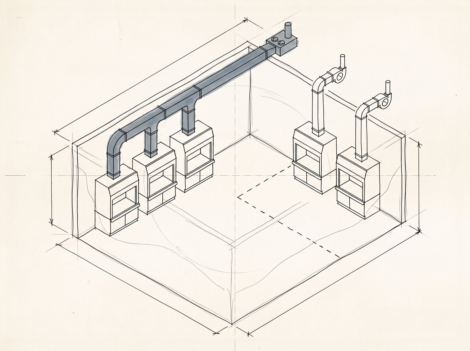
A manifolded laboratory exhaust system is one shared duct. It collects exhaust from two or more fume hoods, or from two or more laboratories. The SUNY construction fund defines it that way in its laboratory design directive. The definition counts sources, not sizes: two hoods in one room that tie into a common duct are manifolded, and a building where every hood has its own fan and its own riser is not. Until you can name the duct that carries two or more sources, you do not have a manifold to evaluate, only a duct to size.
The same directive splits the material question, and the split matters later: the run from the hood connection to the shared duct is welded stainless steel, while the shared exhaust main is galvanized steel. That is a material decision, and it follows the architecture rather than leading it. Decide which sources reach the shared duct first, then let the material follow.
Four Combinations of Duct and Fan
Two separate decisions hide inside the single word manifold: whether the ductwork is shared, and whether the fan group is shared. Keep them apart and four combinations appear, each with its own cost profile and its own failure mode.
| Combination | What it looks like | Where it fits |
|---|---|---|
| Shared duct, shared fan group | Two or more sources into one main, served by a lead-lag fan set | The common manifolded architecture for compatible chemical work |
| Shared duct, separate fans | One main, one fan per source or per group, each discharging into the main | Rare; used when sources can share a path but cannot share a fan curve |
| Separate ducts, shared stack | Independent risers that gather at a single stack | When the chemistry forbids mixing but roof space is scarce |
| Separate ducts, separate fans | One fan and one stack per source | Dedicated exhaust; the default for services that cannot mix |
The first and the fourth combinations are the two architectures most projects weigh, which is why the choice is usually described as manifolded against dedicated. The middle two rows exist, and they are sometimes the right answer. A project that cannot mix two chemistries but has one usable roof area ends up in the third row, and a project that shares a duct for cost reasons but must isolate one fan ends up in the second. Naming the row before you argue about the choice keeps the argument short.
The Layer Order: Architecture Before Duct, Fan and Control
Architecture is the first layer, and three layers follow it. Duct diameter, velocity and material come next, then the fan operating point and static pressure budget, then controls and commissioning. For duct diameter and material, see the fume hood duct sizing guide, which covers that layer. The layer settled here is which sources share a duct, and which sources share a fan group.
The order is not a preference, it is a dependency. A duct cannot be sized before you know which streams it carries, and a fan cannot be selected before you know how many fans the architecture requires. Projects that start with sizing end up with either a shared duct that cannot be balanced or dedicated runs that cost more than the decision required. Naming the layer settles the argument; the other three layers belong to their own owners.
Exhaust Compatibility: The Three Questions That Decide Whether Streams Can Share
Question 1 — Can the Mixture Stay Below Its Lower Explosive Limit?
The first question has a fixed technical answer. The ANSI/ASSP Z9.5 compatibility definition, as transcribed in NIH design guidance, requires that flammable or explosive vapors stay below their lower explosive limit and that the combined streams do not form explosive compounds. Both halves are requirements. A stream can sit below its own limit and still fail the second half if the mixture reacts.
Answering the question takes three inputs: the chemical inventory, the expected quantities, and the worst case rather than the average case. If a stream cannot be judged from the data you have, the answer is not to share it and hope. The two honest exits are independent ducting for that stream, or a documented risk assessment written by the people who own the chemistry. Record the answer with a date and a name, because every later decision on the project leans on this one.
Question 2 — Will the Mixture Deposit, Crystallize or React?
Deposition and crystallization are the second failure route, and they are slower than the first. Perchloric acid work is the classic case: the reason it cannot share a duct is a salt-deposition mechanism that governs perchloric-acid work specifically. The architecture consequence is what matters here. A stream that deposits inside a shared duct turns that duct into a maintenance liability for every hood connected to it.
This question is why the decision moves from material to system. A material choice can be revised in a later design phase; a shared duct that must be cleaned, or a group of hoods that must shut down while one branch is decontaminated, changes how the floor operates for years. If you cannot rule out deposition, the shared duct stops being the cheap option and starts being an operating constraint.
Question 3 — Does the Stream Need Filtration or Scrubbing?
Filtration is the third route, and it changes what the duct is. A duct carrying unfiltered chemical vapor is a duct. A duct carrying a filtered radioisotope stream is a contaminated asset with a service life, a change-out procedure and a waste stream. The Z9.5-2022 exception for radioisotope hoods, as transcribed in the same NIH guidance, permits sharing when HEPA or carbon filtration sits between the hood and the shared duct, and it discourages the arrangement because the filters add static pressure and may require a booster fan.
The consequence for your grouping decision is direct. Where filtration is required, the filter belongs to one source, not to a group, and the duct downstream of it inherits the contamination. That pushes the stream out of the shared group unless the project accepts a shared contaminated asset with a documented service procedure. That rule belongs to the radioisotope requirements, and it changes the architecture.
When Your Institution Is Stricter Than the Standard
Two documents can apply to the same project, and they do not cover the same ground. NIH design guidance requires independent or dedicated exhaust for ducted biosafety cabinets, radioisotope hoods, wet exhaust, perchloric acid hoods and other uses identified by risk assessment. That is an institutional requirement, not a national code, and it binds projects that fall under it. The standard itself excludes high-containment facilities, radioisotope or explosive laboratories and biosafety cabinets from its scope, so treating it as blanket coverage of your building would be a mistake.
The workable rule is that the stricter applicable document governs. Run the three questions against the stricter of your institution’s requirement and the standard, write down which document you applied, and keep that note with the compatibility answer. Every stream on the list lands in one of three states: compatible, incompatible, or undecided. Undecided is a decision to gather data, not a decision to share.
Services That Must Stand Alone
Perchloric Acid: One Hood, One Exhaust Path
Perchloric acid work is excluded from shared exhaust by two independent sources. Clemson’s laboratory ventilation standard requires high-hazard and special-purpose hoods, including perchloric acid and other acid digestion systems, to be exhausted individually rather than through a manifolded system. The Labs21 best practice guide reaches the same conclusion from the other direction: its standard practice for perchloric acid is one dedicated fan per hood. The rule itself, and the mechanism behind it, belong to the perchloric acid fume hood requirements page.
For your grouping decision, this exclusion is absolute and local. Removing one hood from the shared group does not weaken the group; it removes the branch that would otherwise dictate cleaning procedures and shutdown windows for every hood connected to it. Treat the exclusion as the first cut in your grouping exercise, before you run any compatibility comparison.
Radioisotopes: The Filtered Exception and Why It Is Discouraged
Radioisotope hoods sit in a narrower position than perchloric acid hoods. The Z9.5-2022 exception, as transcribed in the same NIH guidance, allows a radioisotope hood to join a shared system when HEPA or carbon filtration sits between the hood and the shared duct, and it discourages that arrangement because the filters raise system static pressure and may require a booster fan. The Labs21 grouping rules permit radioisotope hoods of the same type to be grouped together, which is a different statement from grouping them with general chemical exhaust.
Both readings point to the same grouping rule: radioisotope work forms its own group and never mixes with general chemical exhaust. Independent ducting, filter selection and waste handling belong to the radioisotope fume hood requirements page. The boundary is what matters here: one more service leaves the general shared group.
BSL-3, BSL-4 and Select Agent Work: No Shared Duct
Containment level cuts the largest group out of a shared manifold. The Labs21 compatibility grouping places BSL-3 and BSL-4 laboratories and work involving select agents outside shared exhaust entirely, while BSL-1 and BSL-2 work, including biosafety cabinets used for tissue culture only, may share with chemical fume hoods and general laboratory exhaust. The difference is not the cabinet model; it is the containment boundary the room is built around.
That boundary belongs to the biosafety programme rather than to the exhaust architecture decision. Identify which rooms fall inside that boundary, and remove their exhaust from the shared group before any cost comparison starts. Containment design, cabinet selection and decontamination procedures sit with the biosafety programme.
What the Boundary Means for Your Grouping Decision
The grouping exercise has a fixed order. First remove every service that must stand alone: perchloric acid hoods, radioisotope hoods, BSL-3 and BSL-4 rooms, select agent work, and any stream that needs filtration or scrubbing. Then run the compatibility questions on what remains. Then, and only then, compare the cost and operating profile of a shared manifold against dedicated runs for the survivors.
What normally remains is the largest part of the project: general chemical fume hoods and general laboratory exhaust. A laboratory exhaust manifold is built for that population, and the energy, space and redundancy arguments apply there. The exclusions leave the shared group; general chemical hoods and general lab exhaust stay in it.
Fan Redundancy: Two Frameworks, One Answer
Framework One: The Capacity Threshold
One framework sets fan redundancy by system size. Clemson University’s laboratory ventilation standard requires exhaust systems above 10,000 CFM to provide 100 percent standby capacity or N+1, and systems at or below 10,000 CFM to use two fans at 50 percent capacity each. Those figures are that institution’s requirement rather than an industry-wide mandate, and a project governed by a different standard may land elsewhere. Read them as a worked example of how a capacity threshold is written, then confirm the threshold that binds your project.
SUNY takes the same idea and adds two conditions. Its directive requires N+1 fans with variable frequency drives for soft starting, and it places the fans outside the building at the final discharge point so that all ductwork inside the building stays under negative pressure. Two institutions, two framings of one rule: once exhaust is shared, redundancy is mandatory, and the shape of the redundancy follows the size of the system.
Framework Two: The Risk Level
The second framework ignores size and asks how critical the exhaust is. Greenheck’s reading of the ASHRAE laboratory design levels treats LVDL 0–4 as a scale from low to high risk. LVDL 0, 1 and 2 with a low risk assessment can accept a single fan, which is common for dedicated exhaust serving one hood or one space. LVDL 3 or 4 recommends equipment redundancy, so that containment survives a fan failure. The scale is the same one that drives the rest of the laboratory ventilation design, so the level usually already exists on the project.
The level is assigned by the project’s risk process, not by the exhaust designer. The architecture decision needs one thing from that level: whether a single fan is defensible at all. If the project cannot state its laboratory design level, that gap blocks the redundancy decision regardless of system size.
Combining the Two Without Double-Counting
| Question | Framework one | Framework two |
|---|---|---|
| What it asks | How large is the system? | How critical is the exhaust? |
| Trigger | Total exhaust capacity above or below an institutional threshold | Laboratory design level from the project risk assessment |
| Output | Standby capacity: N+1, 100 percent standby, or two fans at 50 percent | Whether a single fan is acceptable |
| Who sets it | The institution’s design standard | The project risk assessment and its owner |
The two frameworks are not competitors, and both apply. Use the risk level to decide whether redundancy is required at all, and the capacity threshold to decide what shape the redundancy takes. A project can satisfy one and fail the other, which is the reason both answers belong in the decision record next to the number of fans.
What Redundancy Costs in Duct and Roof Space
Redundancy is never free. It adds a second fan, isolation dampers on both sides of each fan so that a running fan cannot pull air backwards through a stopped one, control sequences that alternate lead and lag duty, and roof or penthouse area for the second unit. The Labs21 best practice guide places leakage-rated motorized isolation dampers on both the inlet and the outlet of every fan, and it recommends monitoring damper position from the building automation system.
Where the arithmetic stops is the fan operating point. Fan curves, the static pressure budget and the selection point belong to the fume hood exhaust fan sizing guide, and the two decisions stop at different layers. The manifold decision fixes the fan count and the standby mode; how hard each fan works comes later. The manifold decision fixes fan count and standby mode; the operating point stays with the fan-sizing scope.
Sizing the Manifold for Diversity and Future Hoods
Diversity as a Planning Assumption
Diversity is the ratio of the smallest expected flow to the largest. Put another way, it is the percentage of theoretical maximum flow the system is expected to see. The definition comes from the Labs21 best practice guide on manifolded laboratory exhaust. The guide pairs the definition with a mechanism: bypass dampers close fully once flow reaches the most likely minimum, predicted from the selected diversity factor, and fan speed increases from there. Neither the definition nor the mechanism comes with a recommended number.
That absence is the point. Diversity depends on how many hoods the system serves and how the floor is used, so it is an assumption your project makes and signs rather than a value you look up. A laboratory exhaust manifold sized on an unstated assumption is sized on nothing at all. Write the number, the reason for it and the person who agreed to it into the decision record, then revisit the entry whenever the hood count changes.
Future Capacity: What to Reserve Before Concrete
Future capacity is cheaper to reserve before the building exists than after it opens. The capacity question is about the duct and the fan group rather than about any single hood: how many more hoods could tie into this main without replacing the fans, and which of them would need their own branch flow control. Labs21 treats capacity headroom and future flexibility as part of the case for manifolding, and NIH guidance requires flow control on every chemical fume hood branch, which is what makes adding a hood to a live manifold practical in the first place.
Four entries belong in the decision record here: the hood count today, the plausible growth over the building’s life, whether that growth crosses the institutional capacity threshold that changes the redundancy requirement, and the name of the person who owns the growth assumption. The threshold matters more than the number, because crossing it changes the fan architecture rather than only the duct size.
The System Effect You Pay for at the End of the Run
The last capacity item is the one that never reaches a spreadsheet. Fittings, transitions and elbows add pressure loss that the fan has to overcome, and Labs21 calls this the system effect: avoidable turbulence and pressure drop that shows up at the end of the run rather than at the hood. The guidance that follows is plain and effective. Keep duct runs straight, keep elbows few, and pick the zoning that matches the building instead of the drawing set. Zoning also sets how many isolation dampers and control points the system needs, which lands in the cost estimate rather than in the design preference column.
Zoning is the other half of the same decision. Labs21 allows a shared duct to serve all laboratories or specific groups, usually by floor or by building wing, and notes that one large centralized main serving the whole building maximizes the energy benefit. That choice carries a cost that shows up later: one main means one fan group, and one fan group means a single failure response covering every room connected to it. Zoning, diversity and headroom are the three numbers the sizing depends on, and each one needs a signature.
Energy Savings and the Heat-Recovery Trap
The Three Efficiency Tiers and Their Baseline
The efficiency numbers attached to manifolded exhaust come from the Labs21 best practice guide, and they carry a baseline that usually disappears when they are quoted. Measured against a basic constant-volume manifolded system, the guide’s good design practice reaches roughly 30 percent improvement through three changes: variable-air-volume hoods with bypass dampers, variable speed fan control, and a static pressure reset outside working hours. Its better practice reaches roughly 50 percent through a second set of three: stepped fan operation, variable speed control again, and an assessment of plume dispersion.
Two cautions belong next to those figures. They are measured against a basic constant-volume manifolded baseline rather than against whatever your building runs today, and they are bound to the enhancements listed with them, so quoting the percentage without the measures attached to it means nothing. Jensen Hughes led the recent rewrite of the I2SL best practice guide on this subject. It makes the same point from the other direction: codes and standards have not kept pace with the technology, so prescriptive guidance tends to miss optimization that needs earlier engineering.
The Coil-Type Heat Recovery Exception
Heat recovery on hazardous exhaust meets a constraint before it meets a budget. HPAC Engineering’s account of a laboratory exhaust energy recovery project carries a hard constraint. Some jurisdictions do not allow hazardous containment air through high-efficiency total-energy recovery wheels. The mechanical code backs that reading: its hazardous-exhaust provisions require zero cross contamination. The authority having jurisdiction treated the project as hazardous exhaust on that basis. With wheels ruled out, the team evaluated split passive heat pipes, a fixed plate air-to-air heat exchanger and a run-around coil, then chose a networked run-around heat recovery coil with indirect adiabatic and evaporative cooling. The same project manifolds fume hood exhaust with general laboratory exhaust to capture the recoverable energy. That account is a project report rather than the code text itself.
For the architecture decision, the useful part is the ordering. Heat recovery is a later-layer selection, but the architecture decides whether recovery is available at all, because a shared duct concentrates the exhaust stream that a recovery coil would see and a filtered stream changes where the coil can sit. Confirm applicability with your authority having jurisdiction before the option enters the budget, and do not let a recovery scheme change a compatibility or redundancy answer.
Where the Savings Land
Case numbers exist, and they are case numbers. The Labs21 guide records a college retrofit that replaced 30 dedicated fans with 6 fans on 3 headers, each sized at about 67 percent of full load to leave standby and growth margin, and a federal laboratory that used 6 parallel fans of 20,000 cfm each with one always on standby. It also records a DOE2 comparison of three 50,000 cfm fans, one on standby, at roughly 4,700 dollars per year in energy savings and a simple payback near 8 years, and a 250,000 square foot project where variable frequency drives cut annual operating cost by roughly 100,000 dollars.
Those figures describe other buildings under other utility rates and other operating schedules. They support one conclusion for your decision record: a shared system with variable speed control can produce large operating savings, and the size of the saving depends on the baseline, the rate and the schedule. None of the numbers belongs in a budget as an expected return, and none of them changes a compatibility or redundancy answer. The prerequisites decide whether an efficiency strategy applies; the quoted percentages stay out of the budget either way.
What the Architecture Does to Room Pressure Relationships
Pressure Is a Consequence of Air Balance
Room pressure relationships in a laboratory suite follow the air balance, and the exhaust architecture is one of the inputs to that balance. The mechanism, as described in university design standards and in state compliance guidance, is supply air tracking the exhaust leaving a zone minus a fixed offset, which holds the zone slightly negative relative to its neighbours. Change which hoods share a duct, or change how the shared duct is controlled, and you have changed what the supply side has to track.
Pressure is not a separate system you buy; it is the residue of how much air leaves a room and how much enters it. When the exhaust side changes shape, pressure control has to follow, and the follow-up work runs through the controls and commissioning layers. The architecture record captures that the consequence exists and who owns it.
Why a Shared Duct Changes the Failure Response Across Rooms
A shared duct changes the blast radius of a fault. With dedicated exhaust, a fan failure takes one hood or one room out of service and leaves the rest of the floor alone. With a shared duct, a duct static pressure excursion or a fan fault moves every hood connected to that main at once, and the pressure relationships in several rooms move with them. That is the most underrated consequence of manifolding, and it makes the redundancy decision mandatory.
A second effect comes from where the fans sit. SUNY requires the fans to be outside the building at the final discharge point, which keeps all ductwork inside the building under negative pressure; the same arrangement means a breach in the shared main pulls air inward rather than pushing contaminated air into the room. Both effects belong in the decision record as the failure response for the laboratory exhaust manifold group: which rooms lose containment, for how long, and what the safe response is.
The California Anchor: Variable Volume and Its Statutory Exceptions
One jurisdiction has written laboratory exhaust requirements worth reading as a model, because they show how a variable-volume requirement and its exceptions are framed together. California’s 2022 building energy efficiency standards require laboratory exhaust systems with a minimum circulation rate at or below 10 air changes per hour to be designed for variable volume control, so that zone exhaust and makeup air can drop to the minimum needed for ventilation or for maintaining pressure. The California Energy Commission fact sheet lists the statutory exceptions, which include zones where a code, an authority having jurisdiction or an institutional EHS requirement demands constant volume, perchloric acid hoods, radioisotope hoods, and dust or vapor exhaust that needs a minimum transport velocity.
Two boundaries come attached to that requirement. It applies in California, and laboratories inside medical facilities are exempt. The state compliance reference confirms both the scope and one further point: the standards carry no laboratory-specific mandatory measure beyond the equipment efficiency rules. The same section also limits fan power for new laboratory exhaust systems above 10,000 cfm as one of several compliance paths: 0.85 watts per cfm where filtration, scrubbing or other air treatment is installed, and 0.65 watts per cfm where it is not. Air change rate targets themselves belong to the laboratory air changes per hour page, which covers that decision.
Where the Pressure Decision Belongs
The architecture consequence has three boundaries. Single-room makeup air volume and pressure measurement belong to the fume hood makeup air requirements page, which owns the room-level balance. The zone control sequence and the controller hardware belong to the controls layer. Cleanroom pressure-differential practice, including its numeric values and its classification standards, belongs to a different industry.
The pressure consequence still lands in the decision record. The record names the rooms affected by a shared failure, and the party responsible for the pressure response. The architecture settles part of the pressure question and defines the boundary; the remainder moves to the room-level and controls owners.
Stack Count, Plume, and Re-Entrainment as Consequences of the Architecture
One Stack or Many: The Dilution Arithmetic
Stack count is an output of the architecture rather than an input to it. A shared duct gathers more exhaust into fewer discharge points, and the Labs21 guide quantifies why that matters: at the same exit velocity, wind condition and stack height, the plume from 10,000 cfm rises roughly three times as high as the plume from 1,000 cfm. The same guide frames total dilution as the product of internal dilution, between the contaminant source and the discharge point, and external dilution, between the stack top and the receptor, so more internal dilution reduces how much external dilution the design needs.
It also notes that a single stack is easier to place away from building air intakes than several independent stacks are, and recommends grouping exhaust stacks where the site layout allows so that plume dispersion improves. For the decision record the entry is short: the architecture fixes how many discharge points exist, and the discharge points fix how much dilution is available. What happens at the discharge point itself, including the treatment chain and the final location, belongs to the where does fume hood exhaust go page.
Why Modeling Beats a Fixed Stack Rule
There is a widely quoted minimum discharge height, and it arrives as a secondary attribution rather than a code citation. Greenheck reports that NFPA 45 and ANSI/AIHA Z9.5 suggest a minimum system discharge height of 10 feet to protect people working on the roof. Those standards sit with NFPA and ASSP, and the figure is an order-of-magnitude check, not a design rule. Labs21 goes further and recommends evaluating re-entrainment with a plume dispersion calculation or atmospheric modeling instead of applying a fixed stack standard.
Manufacturer-side options exist for the discharge point itself: engineered high-plume nozzles, dilution belts that entrain outside air, and variable geometry nozzles that hold exit velocity as flow drops. Each one changes the plume rather than the architecture, and each belongs to the discharge-point selection that follows the dispersion study. Pick them with that study in hand, not before it.
Leakage Testing and the Permanent Record
A shared duct carries one acceptance item that dedicated runs do not need in the same form: a whole-system leakage test. Labs21 recommends that manifolded exhaust ductwork be leak-tested as a system and that the responsible engineer record the result in the building’s permanent file. The record matters because the duct is a shared asset, and a leak in a manifolded main affects the pressure balance of every room connected to it rather than only the room nearest the leak.
No single leakage figure applies to every project; the test method and acceptance value come from the project specification and the authority having jurisdiction. What the architecture decision records is that the test is required, that the result is filed, and that the file outlives the project team. The discharge end follows from the architecture, and it carries two studies and one test with it.
The Laboratory Exhaust Manifold Decision Record for Your Mechanical Engineer
The Nine Inputs to Gather First
Nine inputs decide the architecture, and each one changes an answer rather than filling a page.
- The hood schedule: how many fume hoods, where each one sits, and which type each one is.
- The chemical and service list, including the work you expect to add later.
- The service grouping from the compatibility review, with every exclusion named and its owner page identified.
- The future growth plan for the floor or the building, counted in hoods rather than in square feet.
- Your diversity assumption, with the name of the person who agreed to it.
- Whether the project crosses the institutional capacity threshold that changes the redundancy requirement.
- Any constant-volume requirement imposed by a code, an authority having jurisdiction or institutional EHS.
- Roof and shaft constraints, including where a discharge point can sit relative to air intakes.
- Emergency power availability for the exhaust fans.
If an item is missing, record it as open and name the owner. An architecture decision built on a blank line is a decision someone else will reverse later.
Common-Mode Versus Single-Point Failure
The two architectures fail in different shapes, and that difference is the reason the choice is not a plain cost comparison.
| Failure mode | Dedicated exhaust | Shared manifold |
|---|---|---|
| Fan failure | One hood or one room loses exhaust | Every source on the main loses exhaust together |
| Duct static pressure drift | Confined to one run | Moves every hood on the main at once |
| Fan down for service | That unit stops working | Lead-lag or N+1 keeps the main running |
| Incompatible stream enters | Isolated by design | Reaches every hood on the main |
| Roof and shaft demand | One stack and riser per source | Fewer stacks, less shaft area |
Dedicated exhaust spreads risk across many small, independent failures. A shared manifold concentrates risk into one large event, then buys protection back through redundancy, isolation dampers and the compatibility review. Neither column is safer in general; each is safer under different assumptions about chemistry, operating hours and maintenance.
The Decision Record Format
The record fits on one page and carries seven lines: service groups, with what shares, what stands alone, what is undecided and who is chasing the missing data; fan arrangement, with the count, the standby mode and the framework behind it; capacity, with the diversity assumption, the future headroom and the signer; pressure, with the rooms affected by a shared failure and the owner of the response plan; discharge, with the number of points and whether a dispersion study is required; open items, each with an owner and a date; and the date plus the signature of the person accountable for the architecture.
One page is not a style preference. A decision that lives in a meeting gets re-litigated at every value-engineering review, and each round erodes the parts that were hardest to defend. A dated page with named owners survives that pressure, and it lets the mechanical engineer start the duct and fan layers with the architecture already settled.
What Still Needs an AHJ or EHS Ruling
Four items sit outside the design team’s decision, and the record names each one and its owner. The laboratory design level comes from the project risk process. The special-service rules for perchloric acid, radioisotopes and containment work belong to their owner pages and to institutional EHS. Jurisdiction-specific requirements, including any constant-volume mandate, belong to the authority having jurisdiction. Heat recovery applicability on hazardous exhaust needs confirmation before it enters the budget.
To review a laboratory exhaust manifold decision for your project, provide the process chemicals and expected quantities, the hood schedule with locations and types, the exhaust arrangement you are considering, the target face velocity, the available utilities and the project location. XICHENG can use those inputs to confirm what the record still leaves open, and to identify the fan, ductwork and control information that has to be confirmed before the design moves ahead.
A laboratory exhaust manifold decision that is written down, dated and signed is the one that survives the next value-engineering review.
Leave a Reply