




Key Takeaways
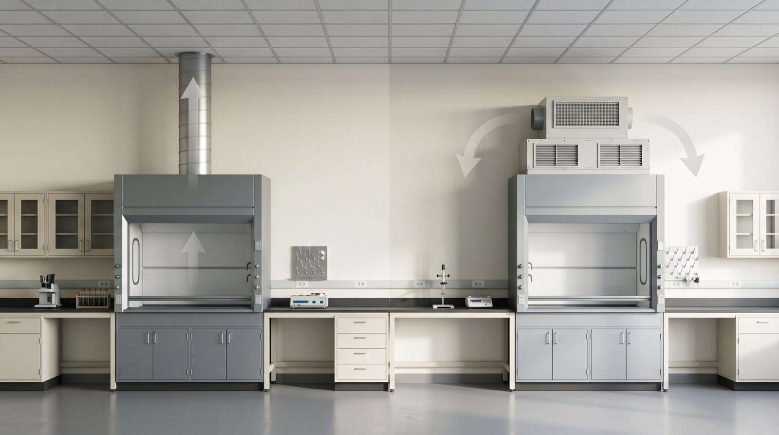
- Fume hood exhaust goes through a treatment train — scrubber, activated carbon — then a fan discharges it from a roof stack. Where does fume hood exhaust go? In a ducted system the air moves from the hood through the duct into a treatment section, and a fan then carries the treated air out of a roof stack; in a ductless system it is filtered and returned to the room.
- The treatment section is a standing part of the ducted path, not an option. A packed-bed scrubber removes water-soluble acid gases such as HCl, HNO3, H2SO4, HF, and NH3, and an activated-carbon stage adsorbs residual VOCs, solvents, and odors; what you install and how you monitor it follows from your chemical inventory and air permit.
- Stacks are tall and fast on purpose. Institutional design benchmarks call for discharge at least 10 ft above the roofline at 3,000 fpm (NIH DRM; UT Tampa), with outdoor intakes kept 40 ft away from exhaust sources (NIH DRM) — the responsible engineer sets the project target against its own source documents.
- Re-entrainment is the failure the design exists to prevent. If stack height, exit velocity, or intake spacing is wrong, discharged air can be drawn back into the building or settle to the ground as downwash.
- Ductless filtration returns air to the room; that is a different destination. Ductless hoods keep the exhaust inside the building, so they are not an “untreated discharge” variant — they change the route entirely.
Where does fume hood exhaust go? In a ducted system, the air drawn from the hood travels through the duct run into a treatment section — typically a packed-bed scrubber followed by an activated-carbon stage — and a fan then discharges the treated air from a roof stack into the atmosphere, where it dilutes and disperses. In a ductless system, the air passes through filters and returns to the room; it never leaves the building. Where do fume hoods vent to? Ducted hoods vent above the building after treatment, through a roof discharge; ductless hoods vent back into the laboratory.
Where Does Fume Hood Exhaust Go? Ducted Discharge Through Treatment vs Ductless Recirculation
Ducted Hoods Discharge Out of the Building — After Treatment
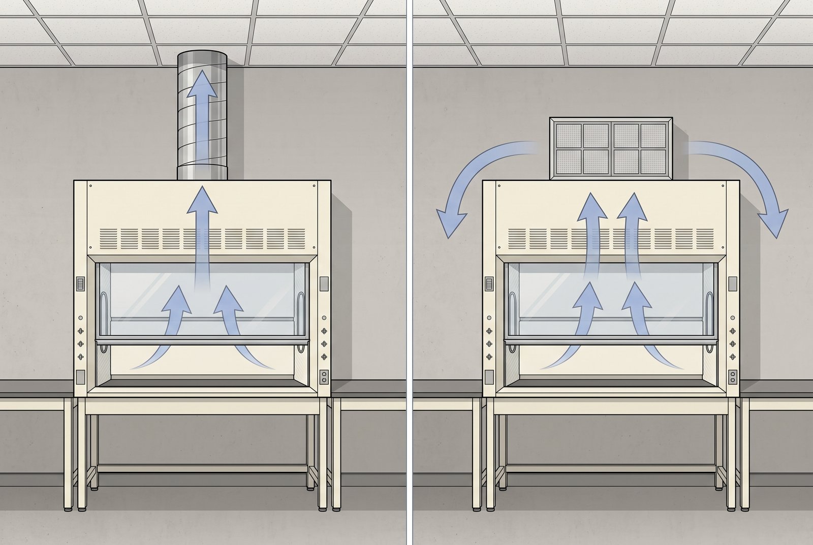
A ducted fume hood is a local exhaust device that captures air at the sash opening and moves it through a dedicated duct run to a discharge point outside the building. Under NFPA 45, the U.S. fire code for laboratory operations, air from chemical fume hoods and special exhaust systems must be discharged above the roof at a location, height, and velocity sufficient to prevent chemical re-entry and personnel exposure.
The ducted route is not a straight pipe to the sky. Between the duct and the fan sits a treatment section whose composition depends on what the lab handles — a scrubber stage for acid gases, an activated-carbon stage for VOCs, solvents, and odors — and the fan then lifts the treated air out of the stack. The stack is the last visible step, but the treatment train is part of the same path.
Ducted discharge is the default for general chemical work because it hands the final dilution job to the atmosphere while keeping contaminants out of the occupied space. Duct sizing and fan selection set the transport numbers behind the sequence — capture, duct, treat, discharge from the roof.
Ductless Hoods Filter the Air and Return It to the Room
A ductless fume hood is the same capture-and-contain principle without the duct run: the air passes through filter media and returns to the room, so the exhaust never leaves the building. NFPA 45’s annex is explicit that these filtered enclosures are not substitutes for chemical fume hoods and that their use requires careful, thorough analysis, so the two routes are not interchangeable.
Choosing between the routes is a selection decision, not a destination guess. The comparison between the two approaches lives in our ducted vs ductless fume hood guide, and the capacity, mobility, and use limits of portable units are covered in our portable vs full-size ductless fume hood article. The destination is what separates the two routes: ducted air is treated and leaves the building; ductless air comes back into the room.
The route your hood follows sets what the destination means for the rest of the discharge path.
The Exhaust Path: From Hood Through Treatment to the Roof Stack and Atmosphere
Step by Step: Cabinet, Duct, Treatment Section, Fan, Roof Stack, Atmosphere
Where does fume hood exhaust go once it leaves the cabinet? In a ducted system, the air moves through five stages in order: out of the hood into the duct run, through the treatment section — scrubber and carbon stages, configured for what the lab uses — to the exhaust fan, and then from the fan out of a roof stack into the atmosphere. Capture at the sash, transport in the duct, treatment as a standing stage, motive power from the fan, discharge above the roof.
Each stage has an owner. Duct sizing and material selection are the job of our fume hood duct sizing guide, and the fan operating point — airflow, static pressure, and control — is the job of our fume hood exhaust fan sizing guide. The order of the path is fixed; duct sizing and fan selection carry the numbers.
Hood Exhaust Is Usually Separate From the Building HVAC
University EHS guidance describes fume hood exhaust as typically separate from the building HVAC supply system: the hood has its own duct, its own fan, and its own discharge point instead of mixing into the general supply air. Separate is the norm because it stops laboratory air from traveling into occupied spaces on a return path.
The consequence shows up in room air balance. When a hood exhausts, it removes room air, and that air has to be replaced while the room stays negative to the corridor. Makeup air volume and laboratory pressure balance are covered in our fume hood makeup air requirements guide.
The Treatment Section Is Part of the Path — Always
The treatment section is not a branch that some projects add and others skip; it is the fixed middle stage of the ducted route. A packed-bed scrubber circulates a reagent — sodium hydroxide or sulfuric acid, depending on the gas — through packing material so that water-soluble acid gases such as HCl, HNO3, H2SO4, HF, and NH3 are absorbed from the airstream, and a demister catches the entrained mist before the air moves on.
Downstream, an activated-carbon stage adsorbs the residual volatile organics, solvent vapors, and odors that a wet scrubber does not remove. Laboratory exhaust is a low-concentration stream — typically 1–50 ppm of the gases of interest — which is why lab-scale treatment is engineered for low-load mass transfer rather than industrial-scale bulk removal, and why its footprint stays compact.
Because the treatment train sits inside the ducted path, its static-pressure drop is part of the system design, and its condition is monitored — pH and differential pressure across the stages are the signals operators watch. The selection logic is the subject of the treatment section below; what matters here is structural: the path has five links, and the treatment section is one of them, in every ducted system.
Every stop between the sash and the sky is accounted for: duct, fan, and makeup air carry their own engineering detail.
Why Stacks Are Tall and Fast: Height, Velocity, and Intake Spacing
The Discharge Must Clear the Roof — and Anyone on It
NFPA 45 requires air from chemical fume hoods and special exhaust systems to be discharged above the roof at a location, height, and velocity sufficient to prevent chemical re-entry and to prevent exposures to personnel. Its annex then recommends that exhaust stacks extend at least 3 m (10 ft) above the highest point on the roof and notes that stacks might need to be much higher to dissipate effluent effectively.
The 10 ft figure is an annex starting point. Because the clause exists to protect people on the roof and to stop re-entry, the design conversation starts there and moves upward when the building, its neighbors, or the local wind patterns require it.
Exit Velocity: 3,000 fpm as an Institutional Benchmark
Institutional design standards quantify the same idea. NIH’s Design Requirements Manual calls for exhaust discharge at least 3 m (10 ft) above the roofline and any roof element within a 4 m (13 ft) radius, with an upward exit velocity of at least 15 m/s — 3,000 fpm — and it lets re-entry calculations push that velocity higher.
The University of Tampa’s lab ventilation standard matches the pair: vertical up-draft discharge at least 10 ft above adjacent rooflines at a minimum exit velocity of 3,000 fpm. Two institutions agree on one number, so 3,000 fpm is a defensible starting target; the responsible engineer or EHS team sets the project value.
Velocity and height work as a pair rather than as independent knobs. Raising stack height without enough exit velocity lets the plume fall back onto the roof; raising velocity alone wastes fan energy without lifting the plume clear.
Velocity and height work as a pair rather than as independent knobs. Raising stack height without enough exit velocity lets the plume fall back onto the roof; raising velocity alone wastes fan energy without lifting the plume clear.
Spacing From Air Intakes: The 40 ft Institutional Benchmark
Intake placement is the third leg of the design. NIH’s DRM requires outdoor air intakes to sit at least 12 m (40 ft) from exhaust-contaminant sources and directs designers to evaluate wind direction, wind velocity, stack effect, building height, and other factors when placing intakes and outlets.
The 40 ft figure is an NIH institutional benchmark; name the source when you use the number and let the project authority settle any gap. Other institutions express the same idea as “locate the discharge with respect to surrounding air inlets to avoid contaminant re-entry” without publishing a distance.
Air Dispersion Modeling Beyond the Distance Rules
Distance rules screen a design; an air dispersion model proves it. NIH’s DRM requires an air dispersion model in addition to the geometric string-distance method when calculating the minimum separation between intake and exhaust, because geometry alone cannot account for wind direction, wind speed, and the concentration of air at an intake.
Modeling is engineer work: the responsible design team runs the air dispersion model. The boundary matters: if your project involves toxic or odorous contaminants, the responsible design team runs the model, and the figures you verify here — 10 ft, 3,000 fpm, 40 ft — are the starting checks, not the final answer.
Three institutional targets — height, exit velocity, and intake spacing — let you check any discharge point against the source documents.
Re-Entrainment and Downwash: When Discharged Air Comes Back
Re-Entrainment: Why the Design Rules Exist
Re-entrainment is the process by which discharged contaminants are drawn back into the building, through its own outdoor air intakes or into the airflows of adjacent buildings. NIH’s DRM frames the design target directly: stack height and discharge velocity exist to overcome the building cavity boundary and avoid re-entrainment of exhaust.
That single failure explains the height, the velocity, and the setback rules alike. NFPA 45’s phrase “sufficient to prevent re-entry” is the requirement; the 10 ft height, the 3,000 fpm velocity, and the intake setback are its quantifications. Treatment reduces what leaves the stack; the stack and its neighbors still decide whether any of it comes back.
Downwash: The Plume That Falls to Ground Level
Downwash is a related failure: the effluent plume settles to ground level because discharge velocity is too low or building airflow pulls the plume downward instead of letting it rise. The University of Tampa standard describes the design goal as providing significant effluent dispersal so that effluent downwash does not occur at ground level.
The design response is the upward draft and the velocity minimum. A vertical, high-speed discharge gives the plume the momentum to clear the building cavity before wind can bend it down; no single check guarantees zero downwash, but the set of checks reduces it.
Who Verifies Re-Entry Risk
Verification is a scheduled activity, not an afterthought. Institutional acceptance practice covers the discharge with smoke and re-entry checks that observe plume direction at the stack and watch whether exhaust is drawn back toward intakes; these checks repeat after installation, before first use, and at least annually.
The formal protocol behind those checks is ASHRAE 110. Here, the point is that re-entry risk is a testable property of the discharge, not a design assumption you accept on faith.
Both failure mechanisms — re-entrainment and downwash — are treated as testable discharge performance.
How the Treatment Section Is Selected: Scrubbers, Activated Carbon, and Monitoring
The Treatment Section Is a Standing Stage of the Ducted Path
Because the treatment section is part of every ducted route, the design question is not “do we treat?” but “what do we treat with, and how do we size and monitor it?” The starting point is the chemical inventory: the acids, bases, solvents, and other volatiles the lab actually handles become the list of contaminants the train must address.
The second input is the air permit and applicable emission limits, which decide how much of each contaminant may leave the stack. Between the inventory and the permit, the configuration falls out: which gases go to the wet scrubber, which residuals go to the carbon bed, and what monitoring points the compliance program needs. Projects that handle perchloric acid or radioactive materials follow the dedicated requirements for those applications rather than a generic train.
Because lab exhaust arrives as a low-concentration stream — typically 1–50 ppm of acid gases compared with the much higher loads in industrial stacks — the equipment is engineered for that scale: compact packed-bed scrubbers and carbon vessels sized for lab airflows, installed on the roof or in a mechanical room, with a small footprint.
What the Scrubber and Carbon Stages Actually Do
A packed-bed scrubber removes water-soluble acid gases — HCl, HNO3, H2SO4, HF, and NH3 are the usual list — by chemical absorption into a circulating reagent stream, typically sodium hydroxide or sulfuric acid chosen for the gas mix. The packing gives the gas and liquid a large contact surface; a demister then strips the entrained droplets so the air leaves the stage dry.
The activated-carbon stage sits after the scrubber and adsorbs what wet chemistry does not catch: residual volatile organic compounds, solvent vapors, and odors. The two stages are normally installed as a train, and their condition is monitored — pH of the recirculating reagent and differential pressure across the media are the standard signals — with the instrumentation wired to the building management system for continuous compliance monitoring.
Neither stage removes everything: match the train to the inventory and the permit, monitor the stages that matter, and route device ratings to the project’s engineer and EHS team for sign-off. When your hazard route matches a general-purpose steel fume hood, the General Purpose Steel Fume Hood product page takes over the specification conversation.
Ductless Filtration Returns Air to the Room
Ductless hoods resemble the same cabinet but change the destination: filtered air returns to the room, so there is no discharge point and no treated-versus-untreated choice. NFPA 45’s annex classifies ductless enclosures as a separate enclosure type from the chemical fume hood, and it requires careful, thorough analysis before any use.
If your route is genuinely ductless, capacity and mobility questions belong to the ducted-versus-ductless and portable-ductless articles linked in the first section, and the Ductless Fume Hood product page carries the specification for that route. The distinction matters: returning air to the room is not the same as treating it and discharging it above the roof.
The treatment section in a ducted path covers which gases go to the scrubber, which residuals go to the carbon stage, and what to monitor; ductless return stays separate from discharge entirely.
Verifying the Discharge: Smoke Checks, Re-Entry Tests, and Who Owns Them
What Discharge Verification Covers
Discharge verification checks two things: the plume behaves as designed, and nothing is drawn back into the building. Institutional acceptance practice runs smoke and re-entry checks that watch the stack plume and confirm exhaust is not returning toward intakes; the schedule is after installation, before first use, and at least annually or after major changes. Treatment-train monitoring — reagent pH, media differential pressure — is a separate daily concern from discharge verification, but both feed the same compliance record.
A design promise without field evidence is an assumption. The “it won’t come back” claim is treated as a tested property: visual plume checks come first, and a formal protocol follows when the operation demands deeper proof.
ASHRAE 110: The Formal Test Protocol
The formal method is ASHRAE 110, the standard for testing the performance of laboratory fume hoods, covering airflow visualization, face-velocity measurement, and tracer-gas containment testing. The complete protocol — test designations, smoke and tracer procedures, and report fields — lives in our ASHRAE 110 fume hood testing guide.
The check itself is a smoke and re-entry observation; running and reading an ASHRAE 110 test needs the test designations, tracer procedures, and report fields.
Inspection Checklists and Whole-System Planning
Routine discharge inspection items — stack blockage, damaged discharge points, corrosion, or airflow alarms — belong on the fume hood inspection checklist page. The project-level sequence that ends at the stack sits in laboratory exhaust system design.
A laboratory design starts from laboratory exhaust system design; a discharge-step question starts from the treatment train and the stack.
The discharge point and the treatment train each carry inspection items, a schedule, and an owning procedure.
Fume Hood Exhaust FAQ
Does fume hood exhaust need air-emission compliance or permits?
Yes, where the operation or the location triggers them. Discharge generally must conform to federal, state, and local air-emission regulations, and NFPA 45 keeps the baseline requirement at above-roof discharge with re-entry prevention. The same compliance program decides what the treatment train must remove and what monitoring it must carry.
Whether a permit or a control device applies depends on the contaminants and the jurisdiction. Permit scope gets settled on the laboratory exhaust system design side, where the sequence runs from hazard inventory to acceptance.
What does the treatment section do in a fume hood exhaust path?
The treatment section is the standing purification stage between the duct run and the fan: a packed-bed scrubber absorbs water-soluble acid gases such as HCl, HNO3, H2SO4, HF, and NH3 into a sodium hydroxide or sulfuric acid reagent stream, a demister removes entrained mist, and an activated-carbon stage adsorbs residual VOCs, solvents, and odors.
What your lab needs in that train depends on the chemical inventory and the air permit. Device-level ratings and approvals are settled by the responsible engineer and EHS team, with dedicated requirements applying to perchloric-acid and radioactive work.
Does a fume hood remove all hazardous vapors?
No hood removes every contaminant under every condition. Containment depends on correct design, correct operation, and periodic performance testing, which is why acceptance testing exists and why ASHRAE 110-type tests are the evidence standard, not the hood’s label. A treatment train reduces what leaves the stack, but it does not change what the hood’s containment does at the bench.
Behavior matters as much as equipment: sash position, work practices, and maintenance define whether the containment the design intends is achieved at the bench.
How often is fume hood exhaust (discharge) verified?
Institutional practice is after installation and before first use, then at least annually, and again after major changes to the hood, its duct, the treatment train, or the building’s airflow. Some operations set shorter intervals based on hazard level.
The cadence above is institutional practice; your EHS office or the applicable inspection program sets the binding schedule, and the fume hood inspection checklist carries the inspection items.
Where Does Fume Hood Exhaust Go? Three Checks Before You Rely on the System
Three Checks Before You Rely on the Exhaust
So what does the exhaust path look like in your lab? After working through the route, the design logic, and the failure modes, run three checks before you rely on the system. First, confirm the route: ducted discharge through treatment, or ductless return. Second, verify the stack against the institutional benchmarks above — height over the roofline, upward exit velocity, and intake separation. Third, confirm the treatment train matches your chemical inventory and that its monitoring points — reagent pH, media differential pressure — are in place, then name who verifies the discharge, and when.
Duct sizing, fan selection, and makeup-air balance carry the engineering detail; where the exhaust goes, what treats it, and which specialist owns each step are settled above.
What Changes as the Project Grows
Daily use behavior decides the same outcome: how you operate the sash, load the hood, and respond to alarms defines whether the discharge story holds at the bench — see our how to use a fume hood guide. At project scale, laboratory exhaust system design carries the full sequence.
Two conditional handoffs complete the picture: a hazard route that matches a general-purpose steel fume hood continues to that product page, and a ductless route continues to the ductless product page. So where does fume hood exhaust go in your lab? Through the duct, through the treatment train, out the stack — or, for a ductless route, back into the room. The answer is now a checklist, not a mystery: know your route, check your stack, confirm your treatment section, schedule your test.
Leave a Reply